
Installation / Operation Instruction Manual

BLP SERIES Install, Operation, and Maintenance Manual
SECTION 3: OPERATION AND CONTROLS
Rev-1 Bradford White • 200 Lafayette St. • Middleville, MI 49333 Page 25 of 83
BrutePlate Manual Phone: (800) 531-2111 • Website: www.BradfordWhite.com 02/26/2020
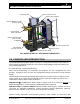
3.5.3 Auto and Manual Control (3-Way Control Valve)
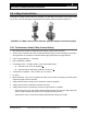
The 3-Way Control Valve Automatic and Manual control modes can be selected using the knob
shown in Figure 3-6.
FIGURE 3-6: Selecting AUTO or MANUAL Control
AUTO Control 3.5.3.1
The control signal is converted by the microprocessor in the electronics module into an output
signal that generates a magnetic field in the core. This causes the only moving part, the
armature, to change its position in accordance with the interacting forces (magnetic field,
counter-spring, hydraulics, and so on). The armature responds rapidly to any change in signal,
transferring the corresponding movement directly to the control disc, enabling fast changes in
load to be corrected quickly and accurately. The valve position is measured continuously. The
positioning controller ensures an exactly proportional relationship between the control signal
and the valve stroke.
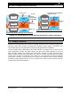
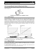
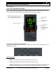
FIGURE 3-7: Valve Characteristics - Equal Percentage (L) and Linear (R)
In the event of a power failure, or if the power is switched off, the spring force closes the valve
automatically (control path ports A → AB normally closed).
Manual Control 3.5.3.2
The valve control path (ports A → AB) can be opened mechanically up to 95% of the full stroke
by pressing the knob inward and turning it clockwise (to the MANUAL position). This disables
the control signal from the controller.
To disable automatic control of the valve, press the knob (Figure 3-6) inward and turn it
counterclockwise (to the OFF position). The valve will close.
EQUAL PERCENTAGE
LINEAR