
Installation / Operation Instruction Manual

BLP SERIES Install, Operation, and Maintenance Manual
SECTION 3: OPERATION AND CONTROLS
Rev-1 Bradford White • 200 Lafayette St. • Middleville, MI 49333 Page 24 of 83
BrutePlate Manual Phone: (800) 531-2111 • Website: www.BradfordWhite.com 02/26/2020
3.5.2 Calibration Instructions (3-Way Control Valve)
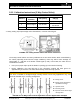
3-WAY CONTROL VALVE DIPSWITCH FUNCTIONS
Switch #
Switch
Function
OFF (down)
ON (up)
1
Characteristic
Linear
Equal percentage*
2
Control signal
0 to 10 Vdc*
2 to 10 Vdc or
4 to 20 mA
3
Volts or mA
0(2) to 10 Vdc*
4 to 20 mA
* Factory setting: equal percentage valve characteristic, 4-20 mA control signal.
FIGURE 3-4: 3-Way Control Valve DIP Switch Functions
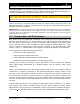
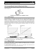
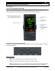
The 3-Way Control Valves are factory-calibrated at 0% and 100% stroke. When commissioning
the valves (especially under extreme usage conditions), there may still be some leakage via
control path A → AB with a 0% stroke control signal (4 mA). In this case, the valve can be
recalibrated as follows:
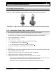
Use a pin or paper clip to push the button in opening (A) in the terminal housing.
During calibration, the LED light (B) in the electronics module will flash green for
approximately 10 seconds. The valve will be briefly closed and fully opened.
CAUTION!
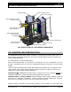
This valve is suitable for straight-through normally closed or three-way applications only, and
should be installed only in a mixing arrangement.
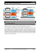
FIGURE 3-5: 3-Way Control Valve Hydraulic Circuits Application Example
A = Mixing circuit
B = Mixing circuit with bypass
(underfloor heating)
C = Injection circuit
D = Diverting circuit
E = Injection circuit with straight-
through valve