
Installation / Operation Instruction Manual

BLP SERIES Install, Operation, and Maintenance Manual
SECTION 3: OPERATION AND CONTROLS
Rev-1 Bradford White • 200 Lafayette St. • Middleville, MI 49333 Page 18 of 83
BrutePlate Manual Phone: (800) 531-2111 • Website: www.BradfordWhite.com 02/26/2020
SECTION 3: OPERATION AND CONTROLS
3.1 INTRODUCTION
This chapter provides information and instructions for following topics:
BLP Series functional description
Preparation of unit for operation
Unit startup procedure instructions
Unit shutdown procedure
instructions
Controller overview & startup
settings
3.2 BLP SERIES FUNCTIONAL DESCRIPTION
BLP Series units are engineered using boiler water or HTHW as the heating medium. Heat
exchanger is plate and frame construction with double wall configuration. BLP Series
incorporates the proven BRADFORD WHITE PID controller coupled with the high efficiency
plate and frame heat exchanger. This water heater is designed to satisfy potable water heating
needs in commercial and institutional environments. The packaged system utilizes simple,
easy-to-understand, real-time load tracking and responsive controls to maintain accurate hot
water temperatures under various load patterns. The BLP Series can be coupled with both
condensing and non-condensing type boilers with wide range of operating temperature ranges to
achieve high efficiency within an optimized space. The control system features temperature
sensors installed on domestic inlet and outlet piping, transmitting a millivolt signal through
quality twisted shielded wiring. The signal transmits directly into the PID controller which, in
turn sends a 4-20 MA signal to the electrically activated three-way control valve to achieve
accurate temperature control over various demand situations.
The BLP Series can efficiently produce higher flow domestic hot water, depending upon the
temperature rise and available boiler water temperature and flow rate. Skid mounted with a
state-of-the-art PID control panel, plate and frame heat exchanger, electric three-way control
valve and non-ferrous circulator pump.
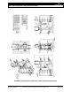
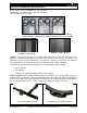
Easy removal of heat exchanger via flanged connections allows the complete removal of the
heat exchanger without disturbing the water heater piping. Isolation valves, inlet strainers and
backflush connections provided for scheduled maintenance.
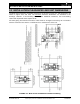
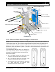
Cold domestic water enters the heat exchanger through the cold water inlet connection (as
shown in Figures 3-1a. It is distributed over the plates in the heat exchanger and flows
downwards. Heated domestic water then exits the heat exchanger from the hot water outlet
connection on bottom of the unit. Unit also includes a constant speed recirculation pump which
continuously circulates the heated domestic water through the heat exchanger to ensure there
is always hot water present in case of demand. Domestic hot water supply temperature is
maintained by either electronic operated 3-way control valve.
Boiler water or HTHW enters the heat exchanger through the inlet connection located on the
bottom and flows upwards to have counter flow arrangement for effective heat transfer. Control
valve which is modulated by the 4-20 mA output from the controller, depending upon the reading
from the temperature sensor on the domestic hot water outlet of the heat exchanger. Unit
employs closed loop feedback control system to maintain target temperature set point in tight
range. Boiler or HTHW exits through the outlet connection on the top of the heat exchanger as
shown. Flow rate of heating medium is modulated to maintain the desired set point in varying
load conditions.
The control panel can be rotated 180 degrees to orient the control surface in the desired
direction.