
Installation / Operation Instruction Manual

BLP SERIES Install, Operation, and Maintenance Manual
SECTION 3: OPERATION AND CONTROLS
Rev-1 Bradford White • 200 Lafayette St. • Middleville, MI 49333 Page 19 of 83
BrutePlate Manual Phone: (800) 531-2111 • Website: www.BradfordWhite.com 02/26/2020
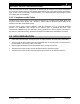
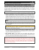
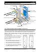
FIGURE 3-1a:
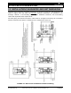
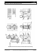
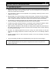
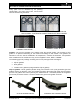
3.2.1 Plate and Frame Heat Exchanger Construction
Frame: The heat exchanger consists of a frame plate (Head), a pressure plate (Follower), a
carrying bar, a lower bar, and a column. Tightening bolts are used to press the plates together.
This is depending on the type of heat exchanger and can be different in some applications.
Plates: The plate package consists of plates with a groove along the rim of the plate and
around the ports. The number of plates is, as well as size and dimension, dependent on the
thermal output required.
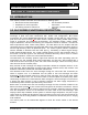
The BRADFORD WHITE plates are designed in
such a way that they both can be used as right and
left plates. The plates just have to be turned 180º.
Right and left plates:
On a right plate the flow runs from hole #2 to
hole #3 or reverse from hole #3 to hole #2.
On a left plate the flow runs from hole #1 to
hole #4 or reverse from hole #4 to hole #1.
The opening of the corner holes are described
in a “plate code index.” For instance, 1234
means that all corner holes are open.
3-WAY CONTROL VALVE
CONTROL PANEL
VALVE
RECIRCULATION PUMP
ISOLATION VALVE
DRAIN VALVE
THERMOCOUPLE
PLATE & FRAME
HEAT EXCHANGER
ISOLATION
VALVES
ISOLATION VALVE & STRAINER
T&P RELIEF VALVE
STRAINER
DRAIN VALVE