BLP SERIES Install, Operation, and Maintenance Manual TABLE OF CONTENTS TABLE OF CONTENTS: SECTION 1: GENERAL INFORMATION .................................................................................................... 4 1.1 INTRODUCTION ........................................................................................................................................... 4 1.2 DESCRIPTION ...............................................................................................................
BLP SERIES Install, Operation, and Maintenance Manual TABLE OF CONTENTS 3.11.5 Modbus/BACnet Data Addresses and Points ...................................................................................................... 36 3.11.6 Instructions to Change Communication Settings Manually ................................................................................ 37 3.12 DRY CONTACTS ...........................................................................................................................
BLP SERIES Install, Operation, and Maintenance Manual SECTION 1: GENERAL INFORMATION SECTION 1: GENERAL INFORMATION 1.1 INTRODUCTION The purpose of this manual is to provide an installation, operation, and maintenance procedural guide for the BLP Series water heaters for boiler water or HTHW to domestic water applications. 1.2 DESCRIPTION The BLP Series water heaters are the engineered solutions for facility owners/managers who need water-to-water heat transfer solution in a small space.
BLP SERIES Install, Operation, and Maintenance Manual SECTION 1: GENERAL INFORMATION 1.3 FEATURES Compact design to fit in small mechanical rooms and standard doorways Complete packaged system with components engineered to specific application requirements Energy efficient High recovery Stainless steel plates Double Wall Plate and Frame heat exchanger ASME compliance heat exchanger 1.
BLP SERIES Install, Operation, and Maintenance Manual SECTION 1: GENERAL INFORMATION 1.6 DESIGN CONDITIONS & CONSTRUCTION The BLP Series units are designed and manufactured from superior materials of highest quality. Each unit meets or exceeds requirements of ASME Section VIII, Div.1 Code. Heat exchangers: Heat exchangers are gasket plate and frame construction and the plates are stainless steel.
BLP SERIES Install, Operation, and Maintenance Manual SECTION 1: GENERAL INFORMATION 1.7 SAFETY 1.7.1 Operating Precautions In order to achieve maximum performance from the unit, the precautions and procedures described below must be strictly followed: The unit should be installed, operated, and serviced only in accordance with the information in this manual.
BLP SERIES Install, Operation, and Maintenance Manual SECTION 1: GENERAL INFORMATION 1.7.4 Safety Notation In this manual there will be four levels of important note types in regards to those accompanying the text of this document. Note headers will appear as shown and described below: NOTE: Important information, but not associated with safety practices. CAUTION! Indicates potential safety concerns, possible material damage, and unsafe practices that may lead to damage of property, injury or death.
BLP SERIES Install, Operation, and Maintenance Manual SECTION 1: GENERAL INFORMATION WARNING! Fluids under pressure may cause injury to personnel or damage to equipment when released. Be sure to shut off all incoming and outgoing water shutoff valves. Carefully decrease all trapped pressures to zero before performing maintenance. Before attempting to perform any maintenance on the unit, shut off all electrical power to the unit from an exterior switch.
BLP SERIES Install, Operation, and Maintenance Manual SECTION 2: INSTALLATION INSTRUCTIONS SECTION 2: INSTALLATION INSTRUCTIONS WARNING! INSTALLER MUST COMPLY WITH STARTUP AND INSTALLATION INSTRUCTIONS TO AVOID A DANGEROUS SITUATION. Startup and installation forms MUST be submitted to a local representative or risk loss of coverage under warranty. The inspection log must be maintained and up-to-date and kept in close proximity to the BLP Series unit for inspection.
BLP SERIES Install, Operation, and Maintenance Manual SECTION 2: INSTALLATION INSTRUCTIONS After the inspection has been completed, we advise that all pressure and control components be checked to assure that they meet design specifications, the name plate and the specification tags. In case of any discrepancy, contact Factory or an authorized sales representative, before proceeding with the installation. 2.1.
BLP SERIES Install, Operation, and Maintenance Manual SECTION 2: INSTALLATION INSTRUCTIONS 2.3 INSTALLATION CLEARANCES AND UNIT DIMENSIONS The BLP Series minimum acceptable clearances are shown in Figure 2-1 and dimensions are shown in Figure 2-2a and 2-2b. The minimum clearance dimensions are indicated in the drawings. However, if local building codes require additional clearances, the local building codes shall supersede these requirements.
BLP SERIES Install, Operation, and Maintenance Manual SECTION 2: INSTALLATION INSTRUCTIONS FIGURE 2-2a: BLP Series Plate and Frame Dimensional Drawing Rev-1 BrutePlate Manual Bradford White • 200 Lafayette St. • Middleville, MI 49333 Phone: (800) 531-2111 • Website: www.BradfordWhite.
BLP SERIES Install, Operation, and Maintenance Manual SECTION 2: INSTALLATION INSTRUCTIONS 2.4 UNIT PLACEMENT The unit should be mounted to the suitable floor, concrete pads, or structural construction, following factory guidelines and applicable architectural and local code requirements to assure the safe operation of the unit. NOTES: 1. Proper rigging techniques should be followed while moving heavy equipment. 2.
BLP SERIES Install, Operation, and Maintenance Manual SECTION 2: INSTALLATION INSTRUCTIONS 2.5 PIPING INSTALLATION AND UNIT CONNECTIONS BLP Series units can be installed in various domestic water applications within the rated temperature and pressure conditions. Refer to Section 6.3 for appropriate Piping and Installation Drawings per your application requirements before making piping connections. CAD drawings are also available on the Bradford White website for layout specification.
BLP SERIES Install, Operation, and Maintenance Manual SECTION 2: INSTALLATION INSTRUCTIONS 2.6 ELECTRICAL CONNECTIONS All field wiring connections for power and controls are inside the control panel at the front of the BLP Series water heater. The wiring label is attached to the inside aluminum door of the control box. An external electrical disconnect (not supplied with the water heater) with adequate overload protection is required.
BLP SERIES Install, Operation, and Maintenance Manual SECTION 2: INSTALLATION INSTRUCTIONS 2.7 WATER QUALITY Before piping the unit into the system, the system must be thoroughly flushed to remove sediment, flux, filings, and other foreign matter. The heat exchanger can be damaged by build-up of corrosion due to sediment. The manufacturer cannot be held responsible for any damage caused by incorrect use of additives in the system.
BLP SERIES Install, Operation, and Maintenance Manual SECTION 3: OPERATION AND CONTROLS SECTION 3: OPERATION AND CONTROLS 3.1 INTRODUCTION This chapter provides information and instructions for following topics: BLP Series functional description Preparation of unit for operation Unit startup procedure instructions Unit shutdown procedure instructions Controller overview & startup settings 3.
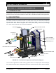
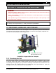
BLP SERIES Install, Operation, and Maintenance Manual SECTION 3: OPERATION AND CONTROLS 3-WAY CONTROL VALVE CONTROL PANEL VALVE ISOLATION VALVES PLATE & FRAME HEAT EXCHANGER STRAINER DRAIN VALVE ISOLATION VALVE & STRAINER RECIRCULATION PUMP T&P RELIEF VALVE THERMOCOUPLE ISOLATION VALVE DRAIN VALVE FIGURE 3-1a: 3.2.1 Plate and Frame Heat Exchanger Construction Frame: The heat exchanger consists of a frame plate (Head), a pressure plate (Follower), a carrying bar, a lower bar, and a column.
BLP SERIES Install, Operation, and Maintenance Manual SECTION 3: OPERATION AND CONTROLS Every plate can be identified by the packing configuration, the plate code index, and thermal short or thermal long execution. START PLATE LEFT HAND FLOW RIGHT HAND FLOW OR WITH GASKET PLATE WITH GASKET END PLATE WITH GASKET THERMAL LONG PLATE THERMAL SHORT PLATE Gaskets: The groove provided in the plates holds the special gasket.
BLP SERIES Install, Operation, and Maintenance Manual SECTION 3: OPERATION AND CONTROLS Glue type gaskets: The surfaces of these gaskets need to be clean and free of oil. Use only chloride free glues, such as Pliobond 20 or 30, Bostic 1782, 3M EC 1099, and Bond Spray 77. Follow the manufacturer’s instructions printed on the cover of the glue. CAUTION! When using commercial solvents and adhesives, follow the manufacturer’s recommendations carefully, as many of these materials are hazardous.
BLP SERIES Install, Operation, and Maintenance Manual SECTION 3: OPERATION AND CONTROLS DOUBLE WALL LEAK IN PLATE CONTAMINATES DOMESTIC WATER AIR GAP GASKET DOMESTIC WATER LEAK IN PLATE VENTS TO EXTERIOR GASKET GASKET AIR GAP BOILER WATER GASKET GASKET GASKET AIR GAP DOMESTIC WATER DOMESTIC WATER SINGLE WALL BOILER WATER DOMESTIC WATER Single Wall Heat Exchanger Cross Section Double Wall Heat Exchanger Cross Section FIGURE 3-2: Double-Wall and Single-Wall Heat Exchanger Leakage Comparison NO
BLP SERIES Install, Operation, and Maintenance Manual SECTION 3: OPERATION AND CONTROLS 3.5 3-Way Control Valve Two types of 3-Way Control Valves are available, one with NPT connections of up to two inches (2”) in size, and one with larger sized flanged connections. Both are shown in Figure 3-3. FIGURE 3-3: 3-Way Control Valves with NPT (left) and Flange Connections (right) 3.5.1 Performance Data (3-Way Control Valve) BLP Series water heaters include MXG-461 3-Way Control Valve actuators.
BLP SERIES Install, Operation, and Maintenance Manual SECTION 3: OPERATION AND CONTROLS 3.5.2 Calibration Instructions (3-Way Control Valve) 3-WAY CONTROL VALVE DIPSWITCH FUNCTIONS Switch Switch # OFF (down) ON (up) Function 1 Characteristic Linear Equal percentage* 2 to 10 Vdc or 2 Control signal 0 to 10 Vdc* 4 to 20 mA 3 Volts or mA 0(2) to 10 Vdc* 4 to 20 mA * Factory setting: equal percentage valve characteristic, 4-20 mA control signal.
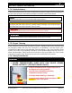
BLP SERIES Install, Operation, and Maintenance Manual SECTION 3: OPERATION AND CONTROLS 3.5.3 Auto and Manual Control (3-Way Control Valve) The 3-Way Control Valve Automatic and Manual control modes can be selected using the knob shown in Figure 3-6. FIGURE 3-6: Selecting AUTO or MANUAL Control 3.5.3.1 AUTO Control The control signal is converted by the microprocessor in the electronics module into an output signal that generates a magnetic field in the core.
BLP SERIES Install, Operation, and Maintenance Manual SECTION 3: OPERATION AND CONTROLS For automatic control, the knob (Fig. 3-6) must be set to the AUTO position (knob will spring out). WARNING! The valve knob (Figure 3-6) MUST be set to AUTO position for proper operation of the BLP Series unit. 3.5.4 3-Way Controller Status LED Indication Open the electronics module of the 3-Way Controller Valve to view the two-color LED display, which indicates the operating status of the valve.
BLP SERIES Install, Operation, and Maintenance Manual SECTION 3: OPERATION AND CONTROLS UNIT STARTUP PROCEDURE INSTRUCTIONS 1) Assure that all manual shutoff valves on boiler water/high temperature hot water and domestic water lines are closed. 2) Slowly open the manual shutoff valve on the cold water inlet line, checking to ensure that there are no leaks at the valve or any joints. 3) Adjust the operating temperature control to the desired temperature. Refer to Section 3.10 and Section 3.
BLP SERIES Install, Operation, and Maintenance Manual SECTION 3: OPERATION AND CONTROLS 3.8 UNIT SHUTDOWN PROCEDURES All maintenance procedures require the water heater to be properly shut down. Follow the instructions below in order to shut down the BLP Series unit: UNIT SHUTDOWN PROCEDURE INSTRUCTIONS 1. Close all valves in the energy source inlet line (boiler water or high temperature water). 2. Turn off all power to the electric control. 3.
BLP SERIES Install, Operation, and Maintenance Manual SECTION 3: OPERATION AND CONTROLS CONTROL BOX 3-WAY CONTROL VALVE DRAIN VALVE (UPPER) BOILER WATER / HTHW OUTLET VALVE COLD WATER INLET VALVE BOILER HOT WATER INLET VALVESTRAINER CIRCULATION PUMP HOT WATER OUTLET VALVE RELIEF VALVE DRAIN VALVE (LOWER) BLP SERIES STARTUP / SHUTDOWN COMPONENTS 3.
BLP SERIES Install, Operation, and Maintenance Manual SECTION 3: OPERATION AND CONTROLS other protocols. 3.9.1 PID Controller Overview This section shows the description of the display and button functions of the controller, which may be required for backup interface when HMI is being replaced or repaired.
BLP SERIES Install, Operation, and Maintenance Manual SECTION 3: OPERATION AND CONTROLS In Levels 3 or Config the Page button will scroll through list headers (no auto-repeat). If the Page button is pressed within a list, the display reverts to the top of the list. The top of the list shows only the list header with no initial parameters. Page (held for >3 seconds): The Goto parameter is selected directly. This operation can be performed from any display.
BLP SERIES Install, Operation, and Maintenance Manual SECTION 3: OPERATION AND CONTROLS 3.10 CONTROLS STARTUP TEMPERATURE CONTROLLER BLP SERIES CONTROL PANEL FRONT PID CONTROLLER Rev-1 BrutePlate Manual Bradford White • 200 Lafayette St. • Middleville, MI 49333 Phone: (800) 531-2111 • Website: www.BradfordWhite.
BLP SERIES Install, Operation, and Maintenance Manual SECTION 3: OPERATION AND CONTROLS 3.11 DATA COMMUNICATIONS BLP Series Water heater control system allows the controller to communicate with external Building Automation System (BAS) or Energy Management System (EMS). It is compatible with standard Modbus RTU or TCP/IP and BACnet UDP/IP multi-protocols without the need for external gateway. Optional gateway is also available for communications with other protocols.
BLP SERIES Install, Operation, and Maintenance Manual SECTION 3: OPERATION AND CONTROLS 3.11.2 Bradford White controller communication features 1. BRADFORD WHITE controller auto-detect the protocol of Modbus TCP/IP, BACnet UDP/IP. a. The two protocols share the same IP addresses, Subnet masks, default gateways. b. Auto-Discovery Mode – known as Zero-configuration networking (zeroconf) i. Utilized Bonjour Service released by Apple under a terms-of-limited-use license. ii.
BLP SERIES Install, Operation, and Maintenance Manual SECTION 3: OPERATION AND CONTROLS 3.11.4 Modbus RTU Communication Wiring NOTE: Up to 32 units can be connected in a daisy chain network including BAS Master. Single unit wiring: Multiple units’ daisy-chain wiring: Rev-1 BrutePlate Manual Bradford White • 200 Lafayette St. • Middleville, MI 49333 Phone: (800) 531-2111 • Website: www.BradfordWhite.
BLP SERIES Install, Operation, and Maintenance Manual SECTION 3: OPERATION AND CONTROLS 3.11.
BLP SERIES Install, Operation, and Maintenance Manual SECTION 3: OPERATION AND CONTROLS 3.11.6 Instructions to Change Communication Settings Manually IP addresses, Subnet Masks and default gateway CAUTION! Do not go to the configuration menu while the controller is operating the water heater. Do not power off the controller without completing all the steps in the configuration settings. Save and go back to the main screen.
BLP SERIES Install, Operation, and Maintenance Manual SECTION 3: OPERATION AND CONTROLS 3. Now release the button. Again press and hold page button appears: 4. Use raise and lower screen: 5. Click on scroll button Rev-1 BrutePlate Manual until following screen buttons in the next step to navigate to the following and you will see passcode screen as shown below: Bradford White • 200 Lafayette St. • Middleville, MI 49333 Phone: (800) 531-2111 • Website: www.BradfordWhite.
BLP SERIES Install, Operation, and Maintenance Manual SECTION 3: OPERATION AND CONTROLS 6. Click on scroll button again to move to the next digit, and use arrow buttons to select the passcode. The default passcode is 0004. 7. If the entered passcode is correct, it will direct to configuration menu screen: 8. Now click on page button 9. Click on page button Rev-1 BrutePlate Manual and you will see following screen: until “COmm” appears on the screen: Bradford White • 200 Lafayette St.
BLP SERIES Install, Operation, and Maintenance Manual SECTION 3: OPERATION AND CONTROLS 10. In order to change the appropriate communication settings: a. Modbus RTU settings - refer to steps 11 and 12 below. Then jump to step 23. b. Modbus/BACnet IP settings - refer to steps 13 through 25. Ignore steps 11 and 12 below. 11. Click on scroll button and you will see F.COm: From the sub-menu, you are able to set up the parameters for Modbus RTU. 12. Now click on scroll button and then click on raise .
BLP SERIES Install, Operation, and Maintenance Manual SECTION 3: OPERATION AND CONTROLS 13. Click on scroll button and you will see “mAIN” screen: 14. Click on raise button to select and you will see , then click on scroll button , (Auto-discovery mode): *Default is OFF. 15. Click on to move to the IP.MODE. Use arrow button to switch the mode: a. is static mode – IP, Gateway, Subnet masks shall be manually setup b. is DHCP mode – DHCP server shall be setup to assign IP, etc.
BLP SERIES Install, Operation, and Maintenance Manual SECTION 3: OPERATION AND CONTROLS 16. Click to move to set up IP addresses. You will see the screen: a. b. Use arrow buttons to change the IP addresses if required. 17. Continue to click to see subnet masks (Indicator: IP.S1, IP.S2, IP.S3, IP.S4): a. Use arrow buttons to change the subnet masks if required. 18. Continue to click to see default gateway (Indicator: IP.G1, IP.G2, IP.G3, IP.G4): a.
BLP SERIES Install, Operation, and Maintenance Manual SECTION 3: OPERATION AND CONTROLS 22. Click to see parameter device ID for BACnet: Use the arrow buttons to change device ID if required. 23. After the setup is complete, press and hold button appears: 24. Click on , until the following screen to go back to the main screen and the settings will be saved. 25. Now the controller is ready for normal operation. Rev-1 BrutePlate Manual Bradford White • 200 Lafayette St.
BLP SERIES Install, Operation, and Maintenance Manual SECTION 3: OPERATION AND CONTROLS 3.12 DRY CONTACTS The following two types of contacts are available for remote monitoring of unit: 3.12.1 Contact closure input (enable/disable) Dry Contacts C and LA are available on the PID temperature controller to remotely start/stop the unit if required. This input is supplied with the current transformer. Contact closure on the remote switch disable (stop) the unit. 3.12.
BLP SERIES Install, Operation, and Maintenance Manual SECTION 4: MAINTENANCE SECTION 4: MAINTENANCE CAUTION! All service on the BLP Series water heaters must be performed by trained and experienced technicians from appropriate service agencies. This section covers the service and maintenance for BLP Series water heaters and provides instructions for the inspection and replacement of critical parts and components.
BLP SERIES Install, Operation, and Maintenance Manual SECTION 4: MAINTENANCE 4.1 CIRCULATING PUMP MAINTENANCE BLP Series water heaters are equipped with a circulating pump to assist in the even heating of the water. If the unit is equipped with a circulating pump, the following procedure should be followed to replace the pump. CIRCULATING PUMP INSPECTION & REPLACE INSTRUCTIONS 1) Take the unit offline (Steps: 1 through 5 of the shutdown procedure, Sec. 3.
BLP SERIES Install, Operation, and Maintenance Manual SECTION 4: MAINTENANCE 4.2 POWER CONNECTION REWIRING If any of the power connections must be rewired at the electrically activated controls or junction boxes, follow the steps listed below. POWER CONNECTION REWIRING INSTRUCTIONS 1) Follow Steps 1 through 5 of the shutdown procedure (Sec. 3.8) to take the unit offline before attempting any electrical service. WARNING! TURN OFF/DISCONNECT ALL ELECTRIC POWER BEFORE ATTEMPTING ANY MAINTENANCE PROCEDURE.
BLP SERIES Install, Operation, and Maintenance Manual SECTION 4: MAINTENANCE 4.3 PLATE HEAT EXCHANGER MAINTENANCE This section describes how to clean and maintain the BLP Series heat exchangers, including disassembly and inspection instructions for the Plate and Frame heat exchangers. 4.3.1 General Heat Exchanger Maintenance Procedures Every six months to one year check temperatures and flows against the commissioning data. Check general condition and look for any signs of leakage.
BLP SERIES Install, Operation, and Maintenance Manual SECTION 4: MAINTENANCE CIP CLEANING INSTRUCTIONS NOTES: Choose a cleaning product appropriate for the materials used in the system that will come into contact with the cleaner. Follow all manufacturer’s instructions when using any cleaning agent. 1) Isolate the heat exchanger from the system and connect the CIP unit to the heat exchanger with the flow direction opposite to normal operation.
BLP SERIES Install, Operation, and Maintenance Manual SECTION 4: MAINTENANCE When CIP cleaning is not appropriate, then it may be necessary to disassemble the Plate and Frame heat exchanger to access the plates directly for cleaning. IMPORTANT! The distance between the inside faces of the Follower frame plate and the Head frame plate (“A” in Figure 4-1) is listed in the service contract.
BLP SERIES Install, Operation, and Maintenance Manual SECTION 4: MAINTENANCE To disassemble the heat exchanger and access the plate assembly for cleaning or replacement, refer to Figure 4-2 and to the instructions that follow. Parts in Figure 4-2 are labeled according to the nomenclature used in the disassembly instructions on the next page. NOTE: Figure 4-2 is for part identification only and is not meant to accurately portray the plate assembly.
BLP SERIES Install, Operation, and Maintenance Manual SECTION 4: MAINTENANCE Below are the instructions for disassembly and inspection of the Plate and Frame heat exchanger. HEX DIASSEMBLY and CLEANING 1. Shut down the heat exchanger as described in Section 3.8. 2. Shut off all water connections. 3. Shut off all power to the unit. 4. Ensure to bleed all pressure from all parts of the unit. Open drain valves. 5. Make sure the heat exchanger cools down to below 104 ºC; with EPDM < 219.2 ºC. 6.
BLP SERIES Install, Operation, and Maintenance Manual SECTION 4: MAINTENANCE 10. Remove the Follower Bracket and Screw (Fig. 4-2) and set aside for reassembly. 11. Pull the Follower frame plate back far enough to expose the internal Plate Assembly (Fig. 4-2). 12. Remove the Splash Guard (Fig. 4-2), and set aside for reassembly. NOTE: The plates must be reassembled in the exact order and configuration, so the order should be recorded or plates marked to ensure proper configuration during reassembly.
BLP SERIES Install, Operation, and Maintenance Manual SECTION 4: MAINTENANCE 4.3.2.2 Plate Inspection and Replacement All plates must be clean, dry, and free from oil or grease for inspection. If there are any oil deposits on the gaskets, or on the gasket seating area, then there is a strong likelihood that the plates may slip out of place when the unit is being tightened. If the gaskets are contaminated with dirt or grit, then these could cause leakage.
BLP SERIES Install, Operation, and Maintenance Manual SECTION 4: MAINTENANCE 4.3.3 Heat Exchanger Reassembly To reassemble the plate and frame heat exchanger refer to the instructions below. HEAT EXCHANGER REASSEMBLY 1. After the plate assembly is in order, refer to Figure 4-2 and instructions in Section 4.3.2 for identification of parts involved in the reassembly. 2. Lightly oil the threads of the tie bolts used for clamping the face plates together.
BLP SERIES Install, Operation, and Maintenance Manual SECTION 4: MAINTENANCE initiate operation of the unit. 12. Unit should be checked for leaks and correct pressure levels to ensure proper operation. 4.4 T&P OR PRESSURE ONLY RELIEF VALVE REPLACEMENT If the water pressure or T&P relief valve mounted on the unit is not functioning correctly and must be replaced, follow the procedures outlined below.
BLP SERIES Install, Operation, and Maintenance Manual SECTION 4: MAINTENANCE T&P VALVE DRAIN VALVE FIGURE 4-4: T&P Relief Valve Replacement Location 4.5 STRAINERS INSPECTION AND REPLACEMENT The strainers are installed upstream of the energy source shutoff valve. The strainers must be flushed periodically (approximately every three (3) to six (6) months) to prevent the buildup of any sediment.
BLP SERIES Install, Operation, and Maintenance Manual SECTION 4: MAINTENANCE the use and/or type of joint compound or sealer at the connections. 9) Follow the startup procedures to put the unit back online. Carefully check all connections for any sign of leakage. 4.6 3-WAY CONTROL VALVE MAINTENANCE The manufacturer documentation included with the unit gives specifics for operation and maintenance of the control valve.
BLP SERIES Install, Operation, and Maintenance Manual SECTION 4: MAINTENANCE ELECTRONICS MODULE 3-WAY CONTROL VALVE PORT B FIGURE 4-5: 3-Way Control Valve Component Locations 3-WAY CONTROL VALVE REPLACEMENT INSTRUCTIONS 1) Follow Steps 1 through 7 of the shutdown procedure in Section 3.8 to take the unit offline before attempting this maintenance procedure. WARNING! Boiler water or high temperature water present situations that can be very dangerous because of the high temperatures and pressures.
BLP SERIES Install, Operation, and Maintenance Manual SECTION 4: MAINTENANCE PORT B BLANKING DISK GASKET NUT FIGURE 4-6: 3-Way Control Valve NPT Connection Components NOTE: NPT screwed valves are flat-faced to facilitate sealing with the gaskets supplied. Do not use hemp, tape, or thread-sealing compound. Do not insulate the actuator. 5) Reattach electrical connections. Follow local codes or accepted contractor practices as to the use and/or type of joint compound or sealer at the connections.
BLP SERIES Install, Operation, and Maintenance Manual SECTION 4: MAINTENANCE Isolation Valves Control Panel –Temperature Controller, etc. Support Frames/Brackets Hardware NOTE: Refer to Sections 4.12 and 4.13 for complete replacement part number information. 4.9 RECOMMENDED SPARE PARTS: TABLE 4-3: RECOMMENDED SPARE PARTS REFERENCE ITEM NO. QUANTITY PER UNIT SEC 4.12 24 1 Recirculation pump SEC 4.12 4 1 Control Valve Actuator Module SEC 4.13 8&9 1 PID Controller SEC 4.
BLP SERIES Install, Operation, and Maintenance Manual SECTION 4: MAINTENANCE 4.10 INSPECTION SCHEDULE Table 4-4, below, summarizes the recommended time intervals for inspection of the water heater, components, inlet and outlet water and energy source lines (boiler water or high temperature water), and power connections. TABLE 4-4: RECOMMENDED INSPECTIONS TIME INTERVAL TABLE TO BE INSPECTED PER 3 6 1 MANUFACTURE WEEKLY MONTHLY MONTHS MONTHS YEAR SPECS.
BLP SERIES Install, Operation, and Maintenance Manual SECTION 4: MAINTENANCE 4.11 PARTS AND ACCESSORIESS COMMON PARTS TABLE 4-5: PLATE AND FRAME/BRAZED PLATE UNITS ITEM NO. PART NO. QUANTITY PART DESCRIPTION 1 10024 1 BASE SKID – BRADFORD WHITE PLATE 2 10025 1 PLATFORM, HEAT EXCHANGER 3 SEE TABLE 4-8 1 D.W.
BLP SERIES Install, Operation, and Maintenance Manual SECTION 4: MAINTENANCE 13 MHRD-15-0050 16 STUD - 5/8”-11 X 3 ''LG - UNC 2A MHRD-01A-0003 16 MHRD-03-0014 2 MHRD-05-0002 2 HEX NUT 5/8”-11 - UNC 2B HEX BOLT - 3/8”-16 X 1.
BLP SERIES Install, Operation, and Maintenance Manual SECTION 4: MAINTENANCE TABLE 4-6: DOMESTIC HOT WATER ASSEMBLY ITEM NO. PART NO.
BLP SERIES Install, Operation, and Maintenance Manual SECTION 4: MAINTENANCE TABLE 4-7: BOILER HOT WATER ASSEMBLY ITEM NO. PART NO. QUANTITY MPART-E-BV-0023 27 1 MPART-E-BV-0024 MPART-2-X-0125 2 MPART-E-BV-0023 28 MPART-E-BV-0024 1 MPART-E-BV-0025 29 30 31 MPART-E-04-0101 1 MPART-E-04-0102 MPART-2-Y-0005-2.
BLP SERIES Install, Operation, and Maintenance Manual SECTION 4: MAINTENANCE 4.12 CONTROL BOX PARTS 6 5 4 3 12 7 8 6 1 11 2 9 10 17 15 13 16 19 18 20 21 1 Rev-1 BrutePlate Manual 14 Bradford White • 200 Lafayette St. • Middleville, MI 49333 Phone: (800) 531-2111 • Website: www.BradfordWhite.
BLP SERIES Install, Operation, and Maintenance Manual SECTION 4: MAINTENANCE TABLE 4-13: CONTROL PANEL PART NUMBERS ITEM PART NO.
BLP SERIES Install, Operation, and Maintenance Manual SECTION 4: MAINTENANCE This page is intentionally left blank Rev-1 BrutePlate Manual Bradford White • 200 Lafayette St. • Middleville, MI 49333 Phone: (800) 531-2111 • Website: www.BradfordWhite.
BLP SERIES Install, Operation, and Maintenance Manual SECTION 5: TROUBLESHOOTING SECTION 5: TROUBLESHOOTING The following table summarizes problems that may be encountered over the life of a BLP Series unit, and the procedures to remedy those problems. The left-hand column lists the symptoms. The remaining columns are suggested procedures or “remedies” that should be followed to identify and correct the problem. SYMPTOM Water heater is not able to maintain the required temperature at the rated capacity.
BLP SERIES Install, Operation, and Maintenance Manual SECTION 5: TROUBLESHOOTING DHW supply temperature is too high. 1. The water heater temperature control system/valve is not operating properly. 1. See the adjustment and testing instructions contained in Section 3.5 for the specific temperature control system installed on the unit. Also, check to ensure that the thermocouple is installed and functioning correctly. Repair or replace thermocouple if needed.
BLP SERIES Install, Operation, and Maintenance Manual SECTION 5: TROUBLESHOOTING Excessive or insufficient boiler water being returned from the unit. Unit is not heating the domestic water and control valve is closed. 1. The water return piping has not been installed properly to allow the water return; boiler water return line is restricted; or the return check valve is leaking or has failed. 2. There is a water leakage in the heat exchanger. 1. 2. 1. 2. 3. Temperature and Pressure or pressure only 4.
BLP SERIES Install, Operation, and Maintenance Manual SECTION 5: TROUBLESHOOTING Water heater shuts down at or too close to (above or below) the design outlet water temperature. 1. Over temperature limit settings not properly set or defective. 1. Refer to adjustment instructions contained in Section 3.11. Replace the defective parts as necessary. 1. Water return piping has not been installed 1.
BLP SERIES Install, Operation, and Maintenance Manual SECTION 5: TROUBLESHOOTING 1. Controller ‘Locks Up.’ 1. Recycle power to the unit by removing AC power, waiting 10 seconds and reconnecting power. DANGER! Controller unit ‘Locks Up.’ This should be done by using the user provided circuit breaker or fuse, not by removing the power wires at the terminal block. Serious injury or death can occur if contact is made with the incoming AC power. HMI and/or 1. Display remains at zero or shows no 1.
BLP SERIES Install, Operation, and Maintenance Manual SECTION 6: TECHNICAL DRAWINGS AND FORMS SECTION 6: TECHNICAL DRAWINGS & FORMS 6.1 DIMENSIONAL DRAWINGS Rev-1 BrutePlate Manual Bradford White • 200 Lafayette St. • Middleville, MI 49333 Phone: (800) 531-2111 • Website: www.BradfordWhite.
BLP SERIES Install, Operation, and Maintenance Manual SECTION 6: TECHNICAL DRAWINGS AND FORMS 6.2 CLEARANCE DRAWINGS Rev-1 BrutePlate Manual Bradford White • 200 Lafayette St. • Middleville, MI 49333 Phone: (800) 531-2111 • Website: www.BradfordWhite.
BLP SERIES Install, Operation, and Maintenance Manual SECTION 6: TECHNICAL DRAWINGS AND FORMS 6.3 PIPING AND INSTALLATION DRAWINGS Rev-1 BrutePlate Manual Bradford White • 200 Lafayette St. • Middleville, MI 49333 Phone: (800) 531-2111 • Website: www.BradfordWhite.
BLP SERIES Install, Operation, and Maintenance Manual SECTION 6: TECHNICAL DRAWINGS AND FORMS Rev-1 BrutePlate Manual Bradford White • 200 Lafayette St. • Middleville, MI 49333 Phone: (800) 531-2111 • Website: www.BradfordWhite.
BLP SERIES Install, Operation, and Maintenance Manual SECTION 6: TECHNICAL DRAWINGS AND FORMS Rev-1 BrutePlate Manual Bradford White • 200 Lafayette St. • Middleville, MI 49333 Phone: (800) 531-2111 • Website: www.BradfordWhite.
BLP SERIES Install, Operation, and Maintenance Manual SECTION 6: TECHNICAL DRAWINGS AND FORMS 6.4 ELECTRICAL WIRING DIAGRAMS/SCHEMATICS Control Box Internal Electrical Wiring Diagram: Rev-1 BrutePlate Manual Bradford White • 200 Lafayette St. • Middleville, MI 49333 Phone: (800) 531-2111 • Website: www.BradfordWhite.
BLP SERIES Install, Operation, and Maintenance Manual SECTION 6: TECHNICAL DRAWINGS AND FORMS Terminal Block Wiring Connections: Rev-1 BrutePlate Manual Bradford White • 200 Lafayette St. • Middleville, MI 49333 Phone: (800) 531-2111 • Website: www.BradfordWhite.
BLP SERIES Install, Operation, and Maintenance Manual SECTION 6: TECHNICAL DRAWINGS AND FORMS FORMS AND RECORDS 6.4.
Installation, Operation, and Maintenance Manual Rev-1 BrutePlate Manual Bradford White • 200 Lafayette St. • Middleville, MI 49333 Phone: (800) 531-2111 • Website: www.BradfordWhite.