
Installation / Operation Instruction Manual

BLP SERIES Install, Operation, and Maintenance Manual
SECTION 3: OPERATION AND CONTROLS
Rev-1 Bradford White • 200 Lafayette St. • Middleville, MI 49333 Page 26 of 83
BrutePlate Manual Phone: (800) 531-2111 • Website: www.BradfordWhite.com 02/26/2020
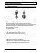
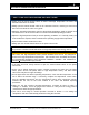
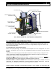
For automatic control, the knob (Fig. 3-6) must be set to the AUTO position (knob will spring
out).
WARNING!
The valve knob (Figure 3-6) MUST be set to AUTO position for proper operation of the BLP
Series unit.
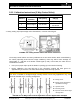
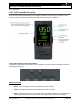
3.5.4 3-Way Controller Status LED Indication
Open the electronics module of the 3-Way Controller Valve to view the two-color LED display,
which indicates the operating status of the valve. The table below identifies what the behavior
and color of the LEDs indicate.
3-WAY CONTROL VALVE STATUS LEDs
LED Display
Status
Description
Green LED
On continuously
Automatic mode: Auto (normal, no faults)
Flashing
– Mechanically set to MANUAL
– Mechanically set to OFF
– Currently in auto-calibration mode
Red LED
On continuously
– General fault
– General calibration fault
– Microcontroller fault
Flashing
– Faulty 24 VAC supply (or low power)
LED Off
– No 24 VAC supply
– Fault with electronics module
The LED will typically only assume only the conditions in this table (continuously red or green,
flashing red or green, or off).
3.6 PREPARATION OF UNIT FOR OPERATION
It is important to make sure that the unit is installed and all piping and electrical connections are
made per instructions in Chapter 2. Also make sure that the connecting piping has been
cleaned out before starting up the unit.
3.7 UNIT STARTUP PROCEDURES
Follow the instructions below to start up the BLP Series unit: