
Installation / Operation Instruction Manual

BLP SERIES Install, Operation, and Maintenance Manual
SECTION 4: MAINTENANCE
Rev-1 Bradford White • 200 Lafayette St. • Middleville, MI 49333 Page 55 of 83
BrutePlate Manual Phone: (800) 531-2111 • Website: www.BradfordWhite.com 02/26/2020
4.3.3 Heat Exchanger Reassembly
To reassemble the plate and frame heat exchanger refer to the instructions below.
HEAT EXCHANGER REASSEMBLY
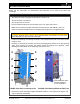
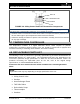
1. After the plate assembly is in order, refer to Figure 4-2 and instructions in Section 4.3.2 for
identification of parts involved in the reassembly.
2. Lightly oil the threads of the tie bolts used for clamping the face plates together. Ensure that
oil or grease do not get onto the gaskets or the gasket seating faces on the back of the
plates.
Wet or contaminated plates can become misaligned during tightening. In that case,
dismantle, clean, and dry all areas in contact with the gaskets.
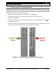
3. Evenly tighten all bolts in the correct order (refer to Figure 4-2a). A ratchet spanner is
advised for this use.
CAUTION!
Tightening the plate package can be done only with a fully depressurized unit.
4. Ensure clamping is as uniform as possible by alternating bolt turns, thus keeping the frames
and plates parallel throughout the operation. Avoid skewing the frame plates by more than 5
mm.
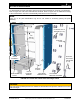
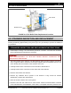
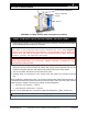
5. Tightening is complete when the distance between the inside faces of both Follower and
Head frame plates equals the “A” distance as shown in the datasheet or measurement (see
Figure 4-1). This tightening distance can also be calculated using the following formula:
Assembly distance = No. of plates x (plate thickness + coefficient) the coefficients vary
depending on the model type. If in doubt, please check with the relevant BRADFORD
WHITE Sales Office.
6. Finally check that all bolts are in tension and clean any spilled oil off the frame plates.
7. On completion the unit can be pressure tested (test pressure is stated on the name plate).
8. If dimension "A" is not reached with application of maximum tightening torque:
a) Check the number of plates and dimension A on the datasheet.
b) Check that all the nuts and bearing boxes are running freely. If not, clean and lubricate
or replace.
9. If the unit does not fully seal, it may be tightened step by step to give dimension “A” min.
This dimension is mentioned on the nameplate. The maximum tightening torque must not,
however, be exceeded.
CAUTION!
Under no circumstances should distance “A” be smaller than “A” min.
10. Replace the Splash Guard, reassemble the Cover Bracket and Screw to the Follower
Cover, and affix the Support Post to the Plate Support Braces at two places (see Figure
4-2).
11. After all adjustments have been made to satisfaction and all connections and fittings
double checked, apply power and refer to Section 3.47: Unit Startup Procedures to