
Installation / Operation Instruction Manual

BLP SERIES Install, Operation, and Maintenance Manual
SECTION 4: MAINTENANCE
Rev-1 Bradford White • 200 Lafayette St. • Middleville, MI 49333 Page 57 of 83
BrutePlate Manual Phone: (800) 531-2111 • Website: www.BradfordWhite.com 02/26/2020
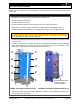
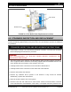
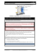
FIGURE 4-4: T&P Relief Valve Replacement Location
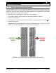
4.5 STRAINERS INSPECTION AND REPLACEMENT
The strainers are installed upstream of the energy source shutoff valve. The strainers must be
flushed periodically (approximately every three (3) to six (6) months) to prevent the buildup of
any sediment.
STRAINERS INSPECTION AND REPLACEMENT INSTRUCTIONS
1) Follow Steps 1 through 7 of the shutdown procedure in Section. 3.2 to take the unit offline
before attempting this maintenance procedure.
WARNING!
TURN OFF/DISCONNECT ALL ELECTRIC POWER BEFORE ATTEMPTING ANY
MAINTENANCE PROCEDURE.
2) The exact location of the strainers can differ between units, but refer to Figure 3-1a and 3-
1b for a typical location. Reference the drawing supplied with the Submittal sheet for the
unit to identify the exact location of the strainers on the unit.
3) Carefully break the line connections on the inlet side of both strainers.
4) Carefully break the line connection on the outlet side of the strainers.
5) Remove and examine the strainers.
6) Remove any sediment that is present in the strainers. If they cannot be cleaned
satisfactorily, replace with new strainers.
7) Place the strainers back-in-line in the system.
8) Reconnect the inlet and outlet lines to each strainer. Follow recommendations contained
in the manufacturer’s documentation, local codes, or accepted contractor practices as to
DRAIN VALVE
T&P VALVE