
Installation / Operation Instruction Manual

BLP SERIES Install, Operation, and Maintenance Manual
SECTION 2: INSTALLATION INSTRUCTIONS
Rev-1 Bradford White • 200 Lafayette St. • Middleville, MI 49333 Page 15 of 83
BrutePlate Manual Phone: (800) 531-2111 • Website: www.BradfordWhite.com 02/26/2020
2.5 PIPING INSTALLATION AND UNIT CONNECTIONS
BLP Series units can be installed in various domestic water applications within the rated
temperature and pressure conditions. Refer to Section 6.3 for appropriate Piping and Installation
Drawings per your application requirements before making piping connections. CAD drawings
are also available on the Bradford White website for layout specification. If any special
application help is needed, please call your local representative or factory for specific
application information.
NOTE:
Also consult local codes and authorities in addition to typical Piping and Installation Drawings.
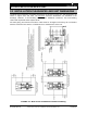
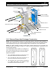
Domestic water piping: The exact location of domestic water inlet and outlet ports of
the unit, as well as pipe diameters and thread/flange size, can be determined for the
drawing supplied with the unit. Properly sized water lines should be connected to the unit.
All piping and fittings should be clean and free of debris. It is important that the piping
systems are balanced when two or more units are in parallel in order to achieve the
combined capacity and proper temperature control. Refer to typical Piping and Installation
Drawings in Section 6.3. The most up-to-date drawings are available at www.dhtnet.com.
NOTE:
Building recirculation piping shall be properly sized to provide sufficient capacity to dissipate
residual heat within the tube bundle of the water heaters during the periods of low demand.
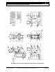
Boiler water piping: Boiler water inlet and return piping to be sized per given flow rates
to the control valve.
CAUTION!
High temperature water can present a very dangerous situation because of the high
pressures and temperatures. Follow all mandatory and recommended procedures and
safety rules to avoid any hazardous situation.
All valves on the source line should be closed during the installation process. Connect
the energy source to the piping leading to the control valve. Determine the exact location
of the inlet connections and piping size using the drawing of the unit. Refer to typical
Piping and Installation Drawings in Section 6.3.
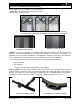
Drain discharge piping: All BLP Series units are equipped with pressure and
temperature relief valves and drain connections on both boiler and domestic water side
connections. They should be piped directly to a safe drain according to appropriate plumbing
codes as explained in Piping and Installation Drawings in Section 6.3.
WARNING!
Make sure that the pressure and temperature relief valve is piped to a proper drain per
instructions and codes. Scalding injury and/or water damage can occur from either the
manual lifting of the lever or the normal operation of the valve if it is not piped to a proper
drain. Ensure that the piping is of the proper material and rating for the temperature and
pressure of the system and that it is secured to prevent possible injury. If the valve fails to flow
water or reseat, consult the factory.