
Installation / Operation Instruction Manual

BLP SERIES Install, Operation, and Maintenance Manual
SECTION 4: MAINTENANCE
Rev-1 Bradford White • 200 Lafayette St. • Middleville, MI 49333 Page 59 of 83
BrutePlate Manual Phone: (800) 531-2111 • Website: www.BradfordWhite.com 02/26/2020
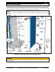
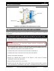
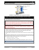
FIGURE 4-5: 3-Way Control Valve Component Locations
3-WAY CONTROL VALVE REPLACEMENT INSTRUCTIONS
1) Follow Steps 1 through 7 of the shutdown procedure in Section 3.8 to take the unit offline
before attempting this maintenance procedure.
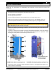
WARNING!
Boiler water or high temperature water present situations that can be very dangerous
because of the high temperatures and pressures. To avoid possible injury or death, use
common sense and follow all accepted and recommended procedures when performing
installation, operation, and maintenance procedures.
WARNING!
TURN OFF/DISCONNECT ALL ELECTRIC POWER BEFORE ATTEMPTING ANY
MAINTENANCE PROCEDURE.
2) Assure that the energy source, water inlets, and outlets have been shut off; that the
pressure has been bled from both the steam and energy source systems; that the unit
has been completely drained; and that all components and surfaces have cooled.
3) Turn off the power and disconnect the leads to the valve.
4) Carefully break all connections to the control valve and remove the old valve from the
unit.
When installing the replacement valve, do not mount with actuator below horizontal position. It
is essential to maintain the specified minimum clearance above and to the side of the actuator
and/or electronics module for servicing, installing, and heat dissipation:
1/2-inch to 1-1/4 inches = 4 inches
1-1/2 inches to 2-1/2 inches = 6 inches
Port "B" can be sealed with the accessories supplied (blanking disk, gasket, and the nut).
NOTE: Blanking disks are not available for the large flange models.
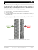
3-WAY CONTROL
VALVE
PORT B
ELECTRONICS MODULE