
Installation / Operation Instruction Manual
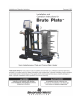

BLP SERIES Install, Operation, and Maintenance Manual
TABLE OF CONTENTS
Rev-1 Bradford White • 200 Lafayette St. • Middleville, MI 49333 Page 3 of 83
BrutePlate Manual Phone: (800) 531-2111 • Website: www.BradfordWhite.com 02/26/2020
3.11.5 Modbus/BACnet Data Addresses and Points ...................................................................................................... 36
3.11.6 Instructions to Change Communication Settings Manually ................................................................................ 37
3.12 DRY CONTACTS ...................................................................................................................................... 44
3.12.1 Contact closure input (enable/disable) ............................................................................................................... 44
3.12.2 Fault Relay Contacts ............................................................................................................................................ 44
SECTION 4: MAINTENANCE ................................................................................................................... 45
4.1 CIRCULATING PUMP MAINTENANCE ...................................................................................................... 46
4.2 POWER CONNECTION REWIRING .......................................................................................................... 47
4.3 PLATE HEAT EXCHANGER MAINTENANCE............................................................................................ 48
4.3.1 General Heat Exchanger Maintenance Procedures ............................................................................................... 48
4.3.2 Clean-In-Place (CIP) Cleaning (Plate and Frame and Brazed Plate) ....................................................................... 48
4.3.3 Heat Exchanger Reassembly .................................................................................................................................. 55
4.4 T&P OR PRESSURE ONLY RELIEF VALVE REPLACEMENT ................................................................................... 56
4.5 STRAINERS INSPECTION AND REPLACEMENT .................................................................................... 57
4.6 3-WAY CONTROL VALVE MAINTENANCE ............................................................................................................ 58
4.6.1 3-Way Control Valve Maintenance ........................................................................................................................ 58
4.6.2 3-Way Control Valve Replacement ........................................................................................................................ 58
4.7 TEMPERATURE CONTROLLER ................................................................................................................ 60
4.8 REPLACEABLE PARTS LIST ..................................................................................................................... 60
4.9 RECOMMENDED SPARE PARTS: ............................................................................................................ 61
4.10 INSPECTION SCHEDULE ........................................................................................................................ 62
4.11 PARTS AND ACCESSORIESS ................................................................................................................. 63
4.12 CONTROL BOX PARTS ............................................................................................................................ 67
SECTION 5: TROUBLESHOOTING ......................................................................................................... 70
SECTION 6: TECHNICAL DRAWINGS & FORMS .................................................................................. 75
6.1 DIMENSIONAL DRAWINGS ....................................................................................................................... 75
6.2 CLEARANCE DRAWINGS .......................................................................................................................... 76
6.3 PIPING AND INSTALLATION DRAWINGS ................................................................................................ 77
6.4 ELECTRICAL WIRING DIAGRAMS/SCHEMATICS ................................................................................... 80
6.5 FORMS AND RECORDS ............................................................................................................................ 82
6.5.1 Water Heater Controller Programming Record Sheet ........................................................................................... 82