
Installation / Operation Instruction Manual


Page 7
Brute Mini
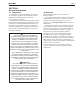
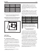
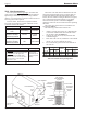
Figure 2B. Closet Installation
Dimensions in inches cm.
6 15
6 15
6 15
4*
10
*6" for models JV160 to JV225.
Note: Clearances listed are manufacturer’s tested values. These
are given as minimum values. Where local and national
codes apply, and values are different than those listed use
the greater value to ensure safe operation.
Minimum Boiler Clearances from Combustible Surfaces.
Dégagements Minimaux à Assurer Entre Ics Parois de
L’appareil et leo Constructions Combustibles
Boiler Sizes 50 - 125 160 - 225
Clearances in cm in cm
Left side 6 15 6 15
Right side 6 15 6 15
Rear 6 15 6 15
Front 4 10 4 10
Flue 6 15 6 15
Top 23 58 36 91
Table 2A Minimum Boiler Clearances
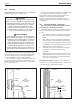
Outside Air Supply: When combustion air is
supplied directly through an outside wall, each
opening should have a minimum free area of one
square inch per 4,000 BTU/h (6 sq. cm per 1.2 kW)
input of the total input rating of all appliances in the
enclosed area.
Inside Air Supply: When combustion is supplied
from inside the building, each opening should have
a minimum free area of one square inch per 1,000
BTU/h (6 sq. cm per 0.3 kW) input of the total input
rating of all appliances in the enclosed area. These
openings should never be less than 100 square inches
(645 sq. cm).
Boiler Size Outside Air Area Inside Air Area
sq. in
sq. cm
sq. in.
sq. cm
50
15
97
100
645
75
20
129
100
645
100
25
161
100
645
125
32
206
125
807
160
40
258
160
1032
225
60
387
225
1452
*Area indicated is for one of two openings: one at floor level
and one at the ceiling, so the total net free area would be
double the figures shown. For special conditions, refer to
NFPA54 ANSI Z223.1. In Canada, refer to the National
Standard CAN1-B149.1 or .2, which differs from this table.
NOTE: Check with louver manufacturers for Net Free Area of
Louvers. Correct for screen resistance to the Net Free Area if a
screen is used.
Table 3. Minimum Recommended
Air Supply to Boiler Room
Exhaust Fans or Vents: Any equipment which
exhausts air from the boiler room can deplete the
combustion air supply or reverse the natural draft
action of venting system. This could cause ue
products to accumulate in the boiler room. Additional
air must be supplied to compensate for such exhaust.
The information in Table 3 is not applicable in
installations where exhaust fans or blowers of any
type are used. Such installations must be designed by
qualied engineers.
If a blower or fan is used to supply air to the boiler
room, the installer should make sure it does not create
drafts which could cause nuisance shutdowns. If a
blower is necessary to provide adequate combustion
air to the boiler, a suitable switch or equivalent must
be wired into the boiler control circuit to prevent the
boiler from ring unless the blower is operating.
The boiler must be completely isolated and
protected from any source of corrosive chemical
fumes such as those emitted by trichloroethylene,
perchloroethylene, chlorine, etc.
SECTION 3.
Air and Venting
3A. Combustion Air Supply
The boiler location must provide sufcient air
supply for proper combustion, and ventilation of
the surrounding area as outlined in the latest edition
of U.S. ANSI standard Z223.1 or in Canada, CAN/
CGA-B149.1 or .2, and any local codes that may be
applicable.
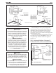
In general, these requirements specify that the
boiler rooms which represent conned spaces should
be provided with two permanent air supply openings;
one within 12 inches (305mm) of the ceiling, the other
within 12 inches (305mm) of the oor.
NOTE: In Canada, follow Canadian Standard,
CAN/CGA-B149 or local codes.