
Installation / Operation Instruction Manual


Page 4
B
RADFORD
W
HITE
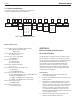
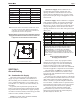
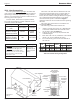
Model NoMeNclature
1st thru 3rd CharaCters (Model designation)
BJV = Bradford White Corp.
Brute Mini
4th CharaCter (ignition systeM)
s = spark ignition
5th thru 7th CharaCters (size)
input MBtu / h
8th CharaCter (fuel)
n = natural gas
p = propane gas
9th CharaCter (firing systeM)
D = on / off
10th CharaCter (ConstruCtion option)
i = (standard)
J = puMp (050-125 only)
11th CharaCter (altitude in feet)
s = (0 - 2,000) natural or (0 - 5,000) propane
h = (2,001 - 5,000) natural
i = (5,001 - 8,000) natural and propane
J = (8,001 - 10,000 natural and propane
12th CharaCter (Country)
u = usa & C
anada
13th CharaCter (reVision)
2 = seCond reVision
MODEL
J V
IGNIT
SYST
S
SIZE
0 5 0
0 7 5
1 0 0
1 2 5
1 6 0
2 2 5
FUEL
N
P
FIRING
SYST
C
D
CONST
OPTION
S
I
J
ALTITUDE
S
H
I
J
REVISION
2
BRADFORD
WHITE
COUNTRY
U
V SJ U 2B
Table 1. Boiler Model Identication.
1 2 4 5 6 7 8 9 10 11 12 13
3
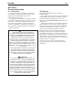
1C. Heater Identication
Consult the rating plate on the boiler. The following
example simplies the heater identication:
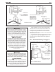
SECTION 2.
Boiler Assembly and Placement
2A. Field Assembly
The Brute Mini is available only with a spark ignition
system and this is indicated on the rating plate, which
can be found on top of the boiler in the right rear corner.
The Bradford White automatic vent dampers are
also standard sizes. And the Bradford White side
wall power venters can be used on sizes. Special
instructions for their installation are included in the
vent damper and power venter package. Read them
carefully before installation.
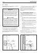
Vent Damper:
1. Brute Mini's have built-in draft diverter for
natural draft operation.
2. Find the vent damper box which is located in the
boiler package.
3. Install the vent damper directly to the top of the
draft diverter outlet with the damper operator
facing to the front of the boiler, and with the ow
direction arrow pointing upward. Use the vent
damper wire harness provided with the boiler
to connect the vent damper to the boiler. The
bracket end of the harness should be connected to
the vent damper actuator.
4. Install the metal plug provided with the vent
damper onto the damper plate hole.