
Installation / Operation Instruction Manual


Page 16
B
RADFORD
W
HITE
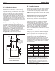
5C Adjusting the bypass:
Refer to Figure 11. Provide a means of measuring
temperature on the inlet pipe to the boiler such as
using a strap on or infrared thermometer. Starting
with both balancing valves fully open, start the boiler.
Adjust the balancing valve on the return to the system
slowly to provide 120°F (44°C) water at the inlet to
the boiler, leaving the bypass balancing valve fully
open. As the system warms up, this valve may need
to be adjusted open. In rare cases, this valve will have
to be kept fully open, and the bypass balancing valve
adjusted toward closed to prevent heated bypass water
from satisfying the call for heat when the system is up
to temperature.
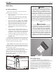
5D Alternate Auto-Bypass Operation
Use of the Bradford White thermostatic union, p/n
2400-030, can provide automatic bypass operation in
primary - secondary piped systems (but cannot be used
when primary - secondary piping is not used). The
thermostatic union is installed on the outlet piping,
after the bypass assembly. It can be used in place of a
balancing valve. It opens fully at 140°F
(see Figure 11). Contact the factory for more
information.
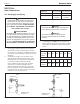
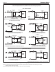
Figure 11. By-pass Piping.
Balancing Valve
or optional thermo-
static union, Bradford
White P/N 2400-030.
(Primary/Secondary
only)
To
System
From
System
In
(Return)
Out
(Supply)
Drip
Leg
Left Side View
A full size by-pass must be installed.
Balancing
Valve
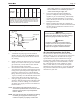
5E Flow Requirements
All high recovery, low volume water boilers must have
adequate ow for efcient operation. Pump selection
is critical to this goal, and pumps should be selected
to provide for system design water temperature rise.
Table 7 details temperature rise and water ow (GPM)
for the Brute Mini boilers.
Damage from improper ow is not warranteed.
Failure to insure proper water ow through the
heat exchanger of the boiler will void the Bradford
White warranty. Flow can be veried by measuring
the difference in water temperatures between the
boiler inlet and outlet. For example: For a JV-100
installation, the inlet water temperature is 160°F
(71°C), and the outlet temperature is 180°F (82°C) at
Normal Input Rate from the rating plate. That means
there is a 20° (11°C) temperature rise through the
boiler. According to Table 7, that would indicate a
ow rate of 8 GPM (0.5L/S). Temperature rise must be
measured with the longest (highest head) zone calling
for heat alone.
Other factors to be considered before selecting a
pump are pipe size, the number of ttings throughout
the system, smoothness of the interior surface of the
pipe, the quantity of water owing through the pipe,
whether a glycol solution is being used, and the total
length of piping in the system. Table 8 provides
example pump selection criteria using Type L copper
piping, one zone valve and up to eight elbows for
single zone systems. Consult the factory or a qualied
system designer if you have more ttings or different
size or type of pipe.
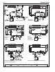
*A circulator and/or primary/secondary piping are required. Consult
factory.
1. Chart is based on 30°F (17°C) maximum temperature rise.
2. Calculations are based on Type L copper tubing with one zone
valve and eight elbows.
3. Typical circulating pumps:
1
/
25
HP=Taco 007, B&G LR-20 or
SLC-25, Grundfos UP15-42F, or equivalent.
1
/
12
HP=B&G LR-
12, Grundfos UP26-42F, or equivalent.
1
/
6
HP=B&G series HV,
Grundfos UP43-75, or equivalent.
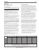
Table 8. Maximum Suggested Circuit Length in Feet.
1/2" Pipe 3/4" Pipe 1" Pipe 1-1/4" Pipe
Size Pump Pump Pump Pump
H.P. H.P. H.P. H.P.
1/25 1/12 1/25 1/12 1/6 1/25 1/12 1/6 1/25 1/12 1/6
50 50 99 390 680
* * * * * * *
75 * 35 160 300 460 640 * * * * *
100 * * 77 150 260 330 620 * * * *
125 * * 27 80 140 170 360 600 * * *
160 * * * 25 72 57 160 330 190 480 *
225 * * * * * * * 110 * 69 330