
Installation / Operation Instruction Manual


Page 10
B
RADFORD
W
HITE
3D-2. Vent Connections
The vent system must be gas tight. All seams and
joints must be sealed with silicone sealant or adhesive
tape having a minimum temperature rating of 400°F
(204ºC). Use at least three corrosion resistant screws at
each slip joint, when required.
For best results, horizontal vent systems should
be as short and straight as possible. Material of vent
connectors shall be as follows:
Description Manufacturer Product
High Temperature
RTV
Dow Corning Trade Mate
2" (51mm) wide
Aluminum foil tape
- adhesively backed
Venture
Product
#3243
2" (51mm) wide
Aluminum foil tape
- adhesively backed
3M Product #433
Vent Sealing Materials.
Materials Vent Length
In U.S.A.: UL type 304, 316 or 294-C
stainless steel or equal 26 gauge minimum.
In Canada: Use "BH-Type" vent
material certied to ULD-S636 Class I
(more than 135°C, but not more than 245°C
ue gas temperature), made of AL29-4C
stainless steel or equal.
Up to a maximum
of 55' (17m) of
equivalent pipe run
(including required
elbows).
Do not use plastic venting of any kind.
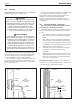
The boiler vent collar must be fastened to the vent
pipe with rustproof metal screws no longer than 1/2”
(13mm) and sealed with high temperature (500ºF /
260ºC) silicone sealant. For larger diameter vent pipes,
use a sealed reducer fastened directly to the boiler
collar and seal all joints as indicated in Figure 7.
Allow the sealant to cure for 24 hours before operating
the boiler.
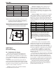
The entire vent system must not exceed the size
specied in Table 4.
The following criteria must be observed:
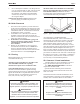
1. Attach a vertical pipe at least 12” (305mm) high
to the boiler outlet before the horizontal run if
run exceeds 5 feet (see Figure 5).
2. Support the vent run at 3’ (.9m) intervals with
overhead hangers.
3. Pitch down the vent run, toward the vent terminal
(hood), 1/4” per foot (20mm per meter).
4. Do not locate any joint screws at the bottom of
the vent run.
Size
Diameter
No. of
Elbows
Horizontal Run Length
in.
mm
ft.
m
50 - 160
4
102
4
35
10.7
225
4
102
2
10
3.0
225
6
152
4
35
10.7
For each elbow eliminated, add 5’ (1.5m) of allowable vent.
Table 4. Horizontal Venting Conguration.
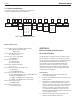
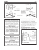
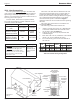
Figure 6. Horizontal Vent Termination.
3 (0.9)
MIN.
VENT TERMINAL
VENT TERMINAL
FORCED
AIR INLET
GRADE
SHEET METAL
SCREWS
THIMBLE
ANCHORED
FASTENER
CAULK JOINTS
SEAL ENTIRE
CIRCUMFERENCE
OF JOINT
ANCHORED
FASTENER
CAULK JOINTS
EXHAUST
HOOD
VENT TERMINAL DETAIL
4 (1.2)
MIN.
4 (1.2)
MIN.
12 (3.7)
MIN.
VENT
TERMINAL
6 (1.8) MIN.
LESS THAN
10
(3.0)
Dimensions in
feet (m).