
Installation / Operation Instruction Manual
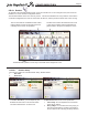
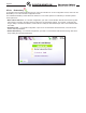
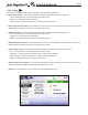
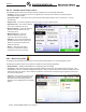
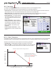
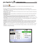
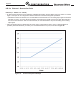
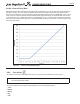
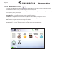
Table Of Contents
- Cover
- TABLE OF CONTENTS
- General Information
- SECTION 2 Venting and Combustion Air
- SECTION 3 Gas supply and Piping
- SECTION 4 Water Flow and Headloss Data
- SECTION 5 Boiler Piping
- SECTION 6 Condensate Drain Trap
- SECTION 7 Electrical Connections
- 7.A Installation Warnings
- 7.B Main Power Connections
- 7.C Main Power Data
- 7.D Control Panel Layout
- 7.E Field Connections
- 7.E.1 Power
- 7.E.2 Dry Contacts
- 7.E.3 Temperature Sensors
- 7.E.4 Safety Chain
- 7.E.5 Isolation Valve
- 7.E.6 Heat Demands
- 7.E.7 Analog In and Analog Out
- 7.E.8 Dry Contacts. Run & Alarm
- 7.E.9 RS 485 for Cascade (Lead Lag)
- 7.E.10 RS485 BMS
- 7.F Modbus to BACnet Memory Map (4 pages)
- 7.G WiringDiagram
- 7.H High Voltage Wiring Diagrams (5 pages)
- 7.I Ladder Diagrams (8 pages)
- SECTION 8 Control Operation
- 8.A The Home Screen
- 8.B Login to Lock / Unlock the Display Screen
- 8.C Quick Start
- 8.D Configuration
- 8.E Service Screens
- 8.E.1 Burner
- 8.E.2 Digital I/O ( Input / Output )
- 8.E.3 Analog I/O
- 8.E.4 Screen Settings Timeout
- 8.E.5 History
- 8.E.6 Restart Touchscreen & Recalibrate
- 8.E.7 Factory Reset
- 8.E.8 HMI Model OEM only
- 8.E.9 BIC Model OEM only
- 8.E.10 Both Model. OEM only.
- 8.E.11 About (the Firmware)
- 8.E.12 O2 (Trim Set Point)
- 8.E.13 LMV
- 8.F Messages and USB
- 8.G Active Demands
- SECTION 9 Parameter Tables (3 pages)
- SECTION 10 Initial startupInstructions
- SECTION 11 Maintenance
- SECTION 12 Troubleshooting
- SECTION 13 Replacement Parts
- 13.A Frame and Jacket Assembly, Part Numbers
- 13.B Control Panel Assembly, Part Numbers
- 13.C Blower and Burner Assembly,Part Numbers. ALL Sizes
- 13.D AC Distribution Box Assemblies and Part Numbers
- 13.E Burner Door Part Numbers
- 13.F Waterway Inlet Assembly, Part Numbers
- 13.G Waterway Outlet Assembly, Part Numbers
- 13.H Gas Train Part Numbers
- 13.I Exhaust Manifold Part Numbers

Page 86
CONFIGURATION
8.D.7.b Flue Limitation Parameters
To navigate to the Flue Limitation Parameters Screen, touch the Temp Limits Icon on the Conguration Screen, then touch
the Flue Limitation button on the Temperature Limits Parameters Screen.
The Flue Limitation Parameters Screen allows adjustment of the following parameters:
•
Manual Reset Flue – The temperature at which the unit will shut down due to exceeding a ue temperature manual reset
condition.
•
Flue Temp MIN & Flue Temp Max- The control will attempt to prevent the unit
from reaching the Manual Reset Flue lockout condition by modulating the fan
speed (and therefore, the input). Flue Temp Min is the temperature setting at
which the unit will begin to de-rate the input. It de-rates linearly until it hits the
Flue Temp Max setting, where the fan is at minimum speed.
8.D.7.c Outlet Limitation Parameters
To navigate to the Outlet Limitation Parameters Screen, touch the Temp Limits Icon on the Conguration Screen, then touch
the Outlet Limitation button on the Temperature Limits Parameters Screen.
The Outlet Limitation Parameters Screen allows adjustment of the following parameters:
• Outlet Temp Min – The outlet temperature at which the boiler will begin to de-rate, in an attempt to prevent a
manual reset high temperature outlet shut down condition.
•
Outlet Temp Max – The outlet temperature at which the boiler will shut down on
a manual reset high temperature outlet condition.