
Installation / Operation Instruction Manual
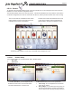
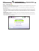
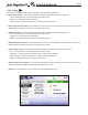
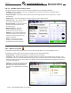
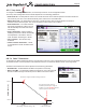
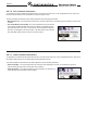
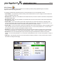
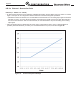
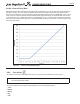
Table Of Contents
- Cover
- TABLE OF CONTENTS
- General Information
- SECTION 2 Venting and Combustion Air
- SECTION 3 Gas supply and Piping
- SECTION 4 Water Flow and Headloss Data
- SECTION 5 Boiler Piping
- SECTION 6 Condensate Drain Trap
- SECTION 7 Electrical Connections
- 7.A Installation Warnings
- 7.B Main Power Connections
- 7.C Main Power Data
- 7.D Control Panel Layout
- 7.E Field Connections
- 7.E.1 Power
- 7.E.2 Dry Contacts
- 7.E.3 Temperature Sensors
- 7.E.4 Safety Chain
- 7.E.5 Isolation Valve
- 7.E.6 Heat Demands
- 7.E.7 Analog In and Analog Out
- 7.E.8 Dry Contacts. Run & Alarm
- 7.E.9 RS 485 for Cascade (Lead Lag)
- 7.E.10 RS485 BMS
- 7.F Modbus to BACnet Memory Map (4 pages)
- 7.G WiringDiagram
- 7.H High Voltage Wiring Diagrams (5 pages)
- 7.I Ladder Diagrams (8 pages)
- SECTION 8 Control Operation
- 8.A The Home Screen
- 8.B Login to Lock / Unlock the Display Screen
- 8.C Quick Start
- 8.D Configuration
- 8.E Service Screens
- 8.E.1 Burner
- 8.E.2 Digital I/O ( Input / Output )
- 8.E.3 Analog I/O
- 8.E.4 Screen Settings Timeout
- 8.E.5 History
- 8.E.6 Restart Touchscreen & Recalibrate
- 8.E.7 Factory Reset
- 8.E.8 HMI Model OEM only
- 8.E.9 BIC Model OEM only
- 8.E.10 Both Model. OEM only.
- 8.E.11 About (the Firmware)
- 8.E.12 O2 (Trim Set Point)
- 8.E.13 LMV
- 8.F Messages and USB
- 8.G Active Demands
- SECTION 9 Parameter Tables (3 pages)
- SECTION 10 Initial startupInstructions
- SECTION 11 Maintenance
- SECTION 12 Troubleshooting
- SECTION 13 Replacement Parts
- 13.A Frame and Jacket Assembly, Part Numbers
- 13.B Control Panel Assembly, Part Numbers
- 13.C Blower and Burner Assembly,Part Numbers. ALL Sizes
- 13.D AC Distribution Box Assemblies and Part Numbers
- 13.E Burner Door Part Numbers
- 13.F Waterway Inlet Assembly, Part Numbers
- 13.G Waterway Outlet Assembly, Part Numbers
- 13.H Gas Train Part Numbers
- 13.I Exhaust Manifold Part Numbers

Page 85
CONFIGURATION
8.D.7 Temp Limits
To navigate to the Temp Limits Screen, touch the Temp Limits Icon on the Conguration Screen.
The Temp Limits Conguration Screen allows adjustment of the following parameters:
• Auto Reset CH– The temperature at which the unit will shut down when outlet temperature exceeds its maximum
auto reset set point. The control will automatically reset, based on the reset dierential.
• Manual Reset CH – The temperature at which the unit will shut down when outlet temperature exceeds its
maximum manual reset set point. The control will require manual reset in this condition.
• Reset Dierential – The value below the
Auto Reset temperature at which the unit
will automatically reset itself and resume
functionality.
• Delta T Parameters– Allows enabling/
disabling of the Delta T derate functionality
and adjustment of the Delta T value at
which the boiler should begin to derate.
• Flue Limitation – Sets the ue temp
limitations.
• Outlet Limitation Parameters – Allows
for the adjustment of Min and Max Outlet
Temps.
FIRING RATE (%)
Max Fire
Min Fire
T
Annunciate a high T condion and begin to derate
Max
= 100F; (hard coded)
Min
(Min seng = 40F; Max seng = 70F;
Default Seng = 60F)
Once max T has been reached,
shutdown (not lockout) on a high T
coon - this will
auto-reset a the
an-short cycle me has expired.
8.D.7.a Delta T Parameters
To navigate to the Delta T Parameters Screen, touch the Temp Limits Icon on the Conguration Screen, then touch the Delta
T Parameters button on the Temperature Limits Parameters Screen. The boiler will derate as shown in the image below.
The Delta T Parameters Screen allows adjustment of the following parameters:
•
Enable/Disable – Enables/disables the Delta T temperature functionality.
•
Delta T Temp Min – The temperature dierence between the unit’s inlet and outlet
at which the boiler will begin to derate to prevent a Delta T auto-reset condition.