
Installation / Operation Instruction Manual
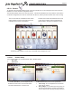
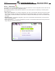
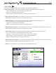
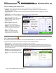
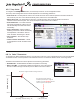
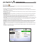
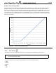
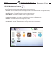
Table Of Contents
- Cover
- TABLE OF CONTENTS
- General Information
- SECTION 2 Venting and Combustion Air
- SECTION 3 Gas supply and Piping
- SECTION 4 Water Flow and Headloss Data
- SECTION 5 Boiler Piping
- SECTION 6 Condensate Drain Trap
- SECTION 7 Electrical Connections
- 7.A Installation Warnings
- 7.B Main Power Connections
- 7.C Main Power Data
- 7.D Control Panel Layout
- 7.E Field Connections
- 7.E.1 Power
- 7.E.2 Dry Contacts
- 7.E.3 Temperature Sensors
- 7.E.4 Safety Chain
- 7.E.5 Isolation Valve
- 7.E.6 Heat Demands
- 7.E.7 Analog In and Analog Out
- 7.E.8 Dry Contacts. Run & Alarm
- 7.E.9 RS 485 for Cascade (Lead Lag)
- 7.E.10 RS485 BMS
- 7.F Modbus to BACnet Memory Map (4 pages)
- 7.G WiringDiagram
- 7.H High Voltage Wiring Diagrams (5 pages)
- 7.I Ladder Diagrams (8 pages)
- SECTION 8 Control Operation
- 8.A The Home Screen
- 8.B Login to Lock / Unlock the Display Screen
- 8.C Quick Start
- 8.D Configuration
- 8.E Service Screens
- 8.E.1 Burner
- 8.E.2 Digital I/O ( Input / Output )
- 8.E.3 Analog I/O
- 8.E.4 Screen Settings Timeout
- 8.E.5 History
- 8.E.6 Restart Touchscreen & Recalibrate
- 8.E.7 Factory Reset
- 8.E.8 HMI Model OEM only
- 8.E.9 BIC Model OEM only
- 8.E.10 Both Model. OEM only.
- 8.E.11 About (the Firmware)
- 8.E.12 O2 (Trim Set Point)
- 8.E.13 LMV
- 8.F Messages and USB
- 8.G Active Demands
- SECTION 9 Parameter Tables (3 pages)
- SECTION 10 Initial startupInstructions
- SECTION 11 Maintenance
- SECTION 12 Troubleshooting
- SECTION 13 Replacement Parts
- 13.A Frame and Jacket Assembly, Part Numbers
- 13.B Control Panel Assembly, Part Numbers
- 13.C Blower and Burner Assembly,Part Numbers. ALL Sizes
- 13.D AC Distribution Box Assemblies and Part Numbers
- 13.E Burner Door Part Numbers
- 13.F Waterway Inlet Assembly, Part Numbers
- 13.G Waterway Outlet Assembly, Part Numbers
- 13.H Gas Train Part Numbers
- 13.I Exhaust Manifold Part Numbers

Page 81
8.D.4.b Rotation
To navigate to the Cascade Rotation Screen, touch the Cascade Icon on the Congure Screen, then touch the
Rotation Icon on the Cascade Conguration Screen.
The Cascade Rotation Screen is a view
only screen. This screen indicates how many units are connected in
a cascade conguration, the order in which each unit will run, and the percent at which each unit is running.
8.D.4.b.1 Rotation Setup
The Rotation Setup button is found only on the boiler that is assigned as ‘Lead’.
For Recurrence Mode, there are two parameters:
1. Time of Day. You can adjust the hour and minute
of the day for rotation.
2. Every X Days. You can select how many days you
want to wait until rotation, and then it will rotate at
the hour and minute of the day previously selected.
There are two options for cascade Rotation Setup, Rotation ‘Mode’:
1. Run Time
2. Recurrence
The red circle with the exclamation mark means
that that boiler is locked out and will need to be
manually reset to return to operations.
The blue circle means that that boiler has a soft
or auto-reset condition and the lead boiler has
placed it later in the queue to attempt to re-re.
In the Run Time Mode, you can adjust only the
Rotation Run Time Hours. This chooses which
unit will re rst based on run time hours.
CONFIGURATION