
Installation / Operation Instruction Manual
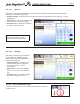
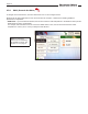
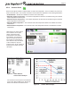
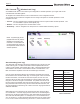
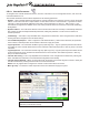
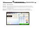
Table Of Contents
- Cover
- TABLE OF CONTENTS
- General Information
- SECTION 2 Venting and Combustion Air
- SECTION 3 Gas supply and Piping
- SECTION 4 Water Flow and Headloss Data
- SECTION 5 Boiler Piping
- SECTION 6 Condensate Drain Trap
- SECTION 7 Electrical Connections
- 7.A Installation Warnings
- 7.B Main Power Connections
- 7.C Main Power Data
- 7.D Control Panel Layout
- 7.E Field Connections
- 7.E.1 Power
- 7.E.2 Dry Contacts
- 7.E.3 Temperature Sensors
- 7.E.4 Safety Chain
- 7.E.5 Isolation Valve
- 7.E.6 Heat Demands
- 7.E.7 Analog In and Analog Out
- 7.E.8 Dry Contacts. Run & Alarm
- 7.E.9 RS 485 for Cascade (Lead Lag)
- 7.E.10 RS485 BMS
- 7.F Modbus to BACnet Memory Map (4 pages)
- 7.G WiringDiagram
- 7.H High Voltage Wiring Diagrams (5 pages)
- 7.I Ladder Diagrams (8 pages)
- SECTION 8 Control Operation
- 8.A The Home Screen
- 8.B Login to Lock / Unlock the Display Screen
- 8.C Quick Start
- 8.D Configuration
- 8.E Service Screens
- 8.E.1 Burner
- 8.E.2 Digital I/O ( Input / Output )
- 8.E.3 Analog I/O
- 8.E.4 Screen Settings Timeout
- 8.E.5 History
- 8.E.6 Restart Touchscreen & Recalibrate
- 8.E.7 Factory Reset
- 8.E.8 HMI Model OEM only
- 8.E.9 BIC Model OEM only
- 8.E.10 Both Model. OEM only.
- 8.E.11 About (the Firmware)
- 8.E.12 O2 (Trim Set Point)
- 8.E.13 LMV
- 8.F Messages and USB
- 8.G Active Demands
- SECTION 9 Parameter Tables (3 pages)
- SECTION 10 Initial startupInstructions
- SECTION 11 Maintenance
- SECTION 12 Troubleshooting
- SECTION 13 Replacement Parts
- 13.A Frame and Jacket Assembly, Part Numbers
- 13.B Control Panel Assembly, Part Numbers
- 13.C Blower and Burner Assembly,Part Numbers. ALL Sizes
- 13.D AC Distribution Box Assemblies and Part Numbers
- 13.E Burner Door Part Numbers
- 13.F Waterway Inlet Assembly, Part Numbers
- 13.G Waterway Outlet Assembly, Part Numbers
- 13.H Gas Train Part Numbers
- 13.I Exhaust Manifold Part Numbers

Page 79
CONFIGURATION
8.D.4.a Cascade Parameters
To navigate to the Cascade Parameters Screen, touch the Cascade Icon on the Conguration Screen, then touch the
Cascade Parameters Icon.
The Cascade Parameters Screen allows
adjustment of the following parameters:
•
Address – When manually addressing each boiler for cascade operations, this parameter is used to set the local boiler
address. Each boiler must have a unique address. A boiler with a value of 1 is the lead boiler. Lag boilers use values
2 through 8. When automatically addressing each boiler, set the lead boiler to a value of 1. With a value of 1, the
Cascade Auto-Cong button is available to use, refer to this parameter below for instructions for automatic addressing
the lag boilers.
•
Dynamic Address – This reects the address of the local boiler after it has been manually or automatically addressed.
After a boiler has been manually/automatically addressed, setting this parameter to 0 will remove the boiler from
cascade operations.
•
Lead Settings – This button is only selectable when congured as the lead boiler. When congured as the lead boiler,
touching this button navigates to the Lead boiler settings.
•
Lost Lead Backup Setpoint – When congured for Cascade Redundancy - Boiler Internal Set Point, this parameter
is the maximum outlet temperature the local boiler is allowed to supply the system.
•
Lag On Hysteresis - The value below the Max Lag Temp (Max Lag Temp – Lag On Hysteresis) that the boiler will turn
on to satisfy an active cascade demand based on the local boiler outlet water temperature. Max Lag Temp is set at the
Lead boiler.
•
Lag O Hysteresis - The value above the Max Lag Temp (Max Lag Temp + Lag O Hysteresis) that
the boiler will turn
o when satisfying an active cascade heat demand based on the local boiler outlet water temperature. Max Lag
Temp is set at the Lead boiler.
•
Cascade Auto-Cong – This is only adjustable at the lead boiler. Once congured as the lead boiler, pressing this
button will initiate the lead boiler to nd and address all lag boilers automatically.
•
Cascade Release Demand - When communications with the master is lost and the lag units continue to satisfy the
cascade heat demand, pressing this button will remove the heat demand.
NOTE: This only applies when congured for cascade - Boiler Internal Set Point Control.
• Max Lag Temp – The maximum outlet temperature each unit is allowed to supply the system.
NOTE: All boilers must be wired for cascade operations prior to
performing Cascade Auto-Cong.