
Installation / Operation Instruction Manual
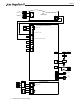

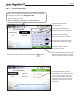
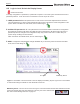
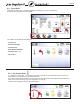

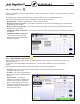
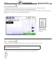
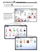

Table Of Contents
- Cover
- TABLE OF CONTENTS
- General Information
- SECTION 2 Venting and Combustion Air
- SECTION 3 Gas supply and Piping
- SECTION 4 Water Flow and Headloss Data
- SECTION 5 Boiler Piping
- SECTION 6 Condensate Drain Trap
- SECTION 7 Electrical Connections
- 7.A Installation Warnings
- 7.B Main Power Connections
- 7.C Main Power Data
- 7.D Control Panel Layout
- 7.E Field Connections
- 7.E.1 Power
- 7.E.2 Dry Contacts
- 7.E.3 Temperature Sensors
- 7.E.4 Safety Chain
- 7.E.5 Isolation Valve
- 7.E.6 Heat Demands
- 7.E.7 Analog In and Analog Out
- 7.E.8 Dry Contacts. Run & Alarm
- 7.E.9 RS 485 for Cascade (Lead Lag)
- 7.E.10 RS485 BMS
- 7.F Modbus to BACnet Memory Map (4 pages)
- 7.G WiringDiagram
- 7.H High Voltage Wiring Diagrams (5 pages)
- 7.I Ladder Diagrams (8 pages)
- SECTION 8 Control Operation
- 8.A The Home Screen
- 8.B Login to Lock / Unlock the Display Screen
- 8.C Quick Start
- 8.D Configuration
- 8.E Service Screens
- 8.E.1 Burner
- 8.E.2 Digital I/O ( Input / Output )
- 8.E.3 Analog I/O
- 8.E.4 Screen Settings Timeout
- 8.E.5 History
- 8.E.6 Restart Touchscreen & Recalibrate
- 8.E.7 Factory Reset
- 8.E.8 HMI Model OEM only
- 8.E.9 BIC Model OEM only
- 8.E.10 Both Model. OEM only.
- 8.E.11 About (the Firmware)
- 8.E.12 O2 (Trim Set Point)
- 8.E.13 LMV
- 8.F Messages and USB
- 8.G Active Demands
- SECTION 9 Parameter Tables (3 pages)
- SECTION 10 Initial startupInstructions
- SECTION 11 Maintenance
- SECTION 12 Troubleshooting
- SECTION 13 Replacement Parts
- 13.A Frame and Jacket Assembly, Part Numbers
- 13.B Control Panel Assembly, Part Numbers
- 13.C Blower and Burner Assembly,Part Numbers. ALL Sizes
- 13.D AC Distribution Box Assemblies and Part Numbers
- 13.E Burner Door Part Numbers
- 13.F Waterway Inlet Assembly, Part Numbers
- 13.G Waterway Outlet Assembly, Part Numbers
- 13.H Gas Train Part Numbers
- 13.I Exhaust Manifold Part Numbers

Page 62
SECTION 8 Control Operation
8.A The Home Screen
8.A.1 Home Screen Active Icons
Figure 32. Active Areas of the Home Screen
Name Icon Description
Security
Displays the current lock status icon. Touch the lock icon to lock or unlock the
Touchscreen Display.
See Section 8.B on page 64
Quick
Start
Provides quick access to the most commonly used parameters for easy installation.
See Section 8.C on page 65
Congure
Provides access to ALL of your congurations for a detailed setup of the unit.
See
Section 8.D on page 69
Service
Allows the service technician to access the basic diagnostic and troubleshooting
information.
See Section 8.E on page 98
Messages
Will show an 'Exclamation Point' when there is a message.
Clicking onto the Message icon will take you to the message itself.
The USB functionality will show the USB Icon at this location, if
being used.
See Section 8.F on page 103
Active
Demands
Will show icons that indicate the active parameters that are currently in
demand.
See Section 8.G on page 104
Navigation
Bar
Top left of every menu. The constant indicator of where you are as you
navigate into and out of the touchscreens. See Section
8.A.2 on page 63
Date &
Time
To change date and time, simply touch the date or time and follow
the directions.
Section 8.D.9 on page 89
LOCKOUTS and ERROR Codes are also show in the
Navigation Bar
when there is one of several
unit Lockouts, Errors or Shut-downs that have occured.
SECTION 12 on page 118
The alarm bell icon indicates that the units alarm has been silenced.
CSP: is the Calculated (and
Current) Set Point. It can be
based on the CH1 (Central Heat
One), CH2, or the DHW (Domestic
Hot Water) setpoint, depending
on the model and the installation
set up and may be adjusted by
the Outdoor Reset and the DHW
Oset.