
Installation / Operation Instruction Manual
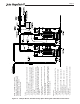

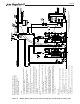
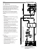
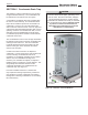

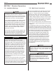
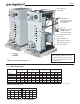

Table Of Contents
- Cover
- TABLE OF CONTENTS
- General Information
- SECTION 2 Venting and Combustion Air
- SECTION 3 Gas supply and Piping
- SECTION 4 Water Flow and Headloss Data
- SECTION 5 Boiler Piping
- SECTION 6 Condensate Drain Trap
- SECTION 7 Electrical Connections
- 7.A Installation Warnings
- 7.B Main Power Connections
- 7.C Main Power Data
- 7.D Control Panel Layout
- 7.E Field Connections
- 7.E.1 Power
- 7.E.2 Dry Contacts
- 7.E.3 Temperature Sensors
- 7.E.4 Safety Chain
- 7.E.5 Isolation Valve
- 7.E.6 Heat Demands
- 7.E.7 Analog In and Analog Out
- 7.E.8 Dry Contacts. Run & Alarm
- 7.E.9 RS 485 for Cascade (Lead Lag)
- 7.E.10 RS485 BMS
- 7.F Modbus to BACnet Memory Map (4 pages)
- 7.G WiringDiagram
- 7.H High Voltage Wiring Diagrams (5 pages)
- 7.I Ladder Diagrams (8 pages)
- SECTION 8 Control Operation
- 8.A The Home Screen
- 8.B Login to Lock / Unlock the Display Screen
- 8.C Quick Start
- 8.D Configuration
- 8.E Service Screens
- 8.E.1 Burner
- 8.E.2 Digital I/O ( Input / Output )
- 8.E.3 Analog I/O
- 8.E.4 Screen Settings Timeout
- 8.E.5 History
- 8.E.6 Restart Touchscreen & Recalibrate
- 8.E.7 Factory Reset
- 8.E.8 HMI Model OEM only
- 8.E.9 BIC Model OEM only
- 8.E.10 Both Model. OEM only.
- 8.E.11 About (the Firmware)
- 8.E.12 O2 (Trim Set Point)
- 8.E.13 LMV
- 8.F Messages and USB
- 8.G Active Demands
- SECTION 9 Parameter Tables (3 pages)
- SECTION 10 Initial startupInstructions
- SECTION 11 Maintenance
- SECTION 12 Troubleshooting
- SECTION 13 Replacement Parts
- 13.A Frame and Jacket Assembly, Part Numbers
- 13.B Control Panel Assembly, Part Numbers
- 13.C Blower and Burner Assembly,Part Numbers. ALL Sizes
- 13.D AC Distribution Box Assemblies and Part Numbers
- 13.E Burner Door Part Numbers
- 13.F Waterway Inlet Assembly, Part Numbers
- 13.G Waterway Outlet Assembly, Part Numbers
- 13.H Gas Train Part Numbers
- 13.I Exhaust Manifold Part Numbers

Page 40
GND
GND
GND
GND
GND
GND
120 N
120 N
120 N
120 N
120 L
120 L
120 L
120 L
24 N
24 N
24 N
24 N
24 L
24 L
24 L
24 L
BOILER PUMP N
BOILER PUMP L
AUXILIARY N
AUXILIARY L
DHW PUMP
DHW PUMP
SYSTEM PUMP
SYSTEM PUMP
ISOLATION VALVE
ISOLATION VALVE
ALARM BELL
ALARM BELL
SYSTEM SUPPLY
SYSTEM SUPPLY
SYSTEM RETURN
SYSTEM RETURN
DHW
DHW
OUTDOOR
OUTDOOR
FIELD INTERLOCK
FIELD INTERLOCK
PROOF OF
CLOSE
PROOF OF
OPEN
TT-1
TT-1
TT-2
TT-2
DHW
DHW
BMS 0-10VDC -
BMS 0-10VDC +
PUMP 0-10VDC -
PUMP 0-10VDC +
RUN - C
RUN - N.C.
RUN - N.O.
ALARM - C
ALARM - N.C.
ALARM - N.O.
CASCADE B
CASCADE A
CASCADE GND
BMS B
BMS A
BMS GND
1
2
3
4
5
6
7
8
9
10
11
12
13
14
15
16
17
18
19
20
21
22
23
24
25
26
27
28
29
30
31
32
33
34
35
36
37
38
39
40
41
42
43
44
45
46
47
48
49
50
51
52
53
54
55
56
57
58
59
60
61
62
63
64
65
66
67
68
69
70
RUN RELAY
CONTACTS
ALARM RELAY
CONTACTS
CASCADE
RS485
BMS RS485
ANALOG
OUTPUT
ANALOG
INPUT
SAFETY
CHAIN
ISOLATION
VALVE
HEAT DEMANDSTEMPERATURE SENSOR INPUTSDRY CONTACTS
POWER
OUTPUTS
120 VAC
H2406100A
24 VAC
Figure 20. Field Connections Terminal Block
Figure 19. Control Panel Components
GND
GND
GND
GND
GND
GND
120 N
120 N
120 N
120 N
120 L
120 L
120 L
120 L
24 N
24 N
24 N
24 N
24 L
24 L
24 L
24 L
BOILER PUMP N
BOILER PUMP L
AUXILIARY N
AUXILIARY L
DHW PUMP
DHW PUMP
SYSTEM PUMP
SYSTEM PUMP
ISOLATION VALVE
ISOLATION VALVE
ALARM BELL
ALARM BELL
SYSTEM SUPPLY
SYSTEM SUPPLY
SYSTEM RETURN
SYSTEM RETURN
DHW
DHW
OUTDOOR
OUTDOOR
FIELD INTERLOCK
FIELD INTERLOCK
PROOF OF
CLOSE
PROOF OF
OPEN
TT-1
TT-1
TT-2
TT-2
DHW
DHW
BMS 0-10VDC -
BMS 0-10VDC +
PUMP 0-10VDC -
PUMP 0-10VDC +
RUN - C
RUN - N.C.
RUN - N.O.
ALARM - C
ALARM - N.C.
ALARM - N.O.
CASCADE B
CASCADE A
CASCADE GND
BMS B
BMS A
BMS GND
1
2
3
4
5
6
7
8
9
10
11
12
13
14
15
16
17
18
19
20
21
22
23
24
25
26
27
28
29
30
31
32
33
34
35
36
37
38
39
40
41
42
43
44
45
46
47
48
49
50
51
52
53
54
55
56
57
58
59
60
61
62
63
64
65
66
67
68
69
70
RUN RELAY
CONTACTS
ALARM RELAY
CONTACTS
CASCADE
RS485
BMS RS485
ANALOG
OUTPUT
ANALOG
INPUT
SAFETY
CHAIN
ISOLATION
VALVE
HEAT DEMANDS
TEMPERATURE SENSOR INPUTSDRY CONTACTS
POWER
OUTPUTS
120 VAC
H2406100A
24 VAC
LMV Controller Assembly
Low Water Cut-O
Handset, Display and
Operating Unit.
For Certied and
Trained Field
Techs Only.
12 Volt DC Power
Supply
Linc Controller
Assembly
O2 Sensor
Controller
Field Connections
Terminal Block
7.D Control Panel Layout
7.E Field Connections
Wiring for all eld connections must be run through the
available electrical conduit to the low voltage box at the
back of the unit. See Figure 18.
Refer to Figure 20 in reference to Sections 7.E.1 thru
7.E.10
7.E.1 Power
Boiler Pump – If connecting a boiler contactor or pump,
use terminals 23 (neutral) and 24 (line voltage). The
output of these terminals is 120VAC with a maximum
output current of 1.5 amps. Boiler pump functionality is
congured using the touch screen.
Auxiliary – no functionality is available on this unit.
7.E.2 Dry Contacts
DHW Pump - If connecting a domestic hot water (DHW)
pump, use terminals 27 and 28 (See Figure 20). This is
a dry contact. The DHW pump supply voltage or DHW
pump relay coil voltage should be applied at terminal
27, and when the DHW pump is called, would be switch
to terminal 28. Contact ratings are 250VAC, 1.5A