
Installation / Operation Instruction Manual
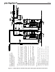

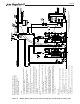
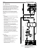
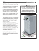

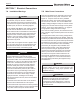
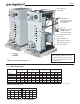

Table Of Contents
- Cover
- TABLE OF CONTENTS
- General Information
- SECTION 2 Venting and Combustion Air
- SECTION 3 Gas supply and Piping
- SECTION 4 Water Flow and Headloss Data
- SECTION 5 Boiler Piping
- SECTION 6 Condensate Drain Trap
- SECTION 7 Electrical Connections
- 7.A Installation Warnings
- 7.B Main Power Connections
- 7.C Main Power Data
- 7.D Control Panel Layout
- 7.E Field Connections
- 7.E.1 Power
- 7.E.2 Dry Contacts
- 7.E.3 Temperature Sensors
- 7.E.4 Safety Chain
- 7.E.5 Isolation Valve
- 7.E.6 Heat Demands
- 7.E.7 Analog In and Analog Out
- 7.E.8 Dry Contacts. Run & Alarm
- 7.E.9 RS 485 for Cascade (Lead Lag)
- 7.E.10 RS485 BMS
- 7.F Modbus to BACnet Memory Map (4 pages)
- 7.G WiringDiagram
- 7.H High Voltage Wiring Diagrams (5 pages)
- 7.I Ladder Diagrams (8 pages)
- SECTION 8 Control Operation
- 8.A The Home Screen
- 8.B Login to Lock / Unlock the Display Screen
- 8.C Quick Start
- 8.D Configuration
- 8.E Service Screens
- 8.E.1 Burner
- 8.E.2 Digital I/O ( Input / Output )
- 8.E.3 Analog I/O
- 8.E.4 Screen Settings Timeout
- 8.E.5 History
- 8.E.6 Restart Touchscreen & Recalibrate
- 8.E.7 Factory Reset
- 8.E.8 HMI Model OEM only
- 8.E.9 BIC Model OEM only
- 8.E.10 Both Model. OEM only.
- 8.E.11 About (the Firmware)
- 8.E.12 O2 (Trim Set Point)
- 8.E.13 LMV
- 8.F Messages and USB
- 8.G Active Demands
- SECTION 9 Parameter Tables (3 pages)
- SECTION 10 Initial startupInstructions
- SECTION 11 Maintenance
- SECTION 12 Troubleshooting
- SECTION 13 Replacement Parts
- 13.A Frame and Jacket Assembly, Part Numbers
- 13.B Control Panel Assembly, Part Numbers
- 13.C Blower and Burner Assembly,Part Numbers. ALL Sizes
- 13.D AC Distribution Box Assemblies and Part Numbers
- 13.E Burner Door Part Numbers
- 13.F Waterway Inlet Assembly, Part Numbers
- 13.G Waterway Outlet Assembly, Part Numbers
- 13.H Gas Train Part Numbers
- 13.I Exhaust Manifold Part Numbers

Page 39
Figure 18. Electrical Connections
Field Electrical
Connections at the
Terminal Block on the
Control Panel
Flex Conduit for
Field Wiring
Available Knockouts for
other wiring needs
Low Voltage Box for Field
Connections
High Voltage Box for
Main Power Connections
VIEW from
the
BACK
Hinged Control Panel
swings open for
servicing and setup
Table 16. Electrical Data
Three Phase
600 480 208
L1 P BR Blk
L2 V O Red
L3 T Y BL
Single Phase
120 240 208
L1 Blk Blk Blk
L2 Wht Red Red
Table 17. Voltage Phase Color Identication
7.C Main Power Data
NOTES: Field Wiring and Main Power
Wiring should only enter at the rear of
the boiler and at these electrical boxes.
The top covers must remain removable
for routine service.
FLA = Full Load Amperage MCA = Minimum Circuit Ampacity MOP = Max Over-current Protection
Electrical
Data
Voltage FLA MCA MOP FLA MCA MOP FLA MCA MOP FLA MCA MOP
120V, 1 phase 5.0 6.2 15.0 6.2 7.8 15.0 7.8 9.7 20.0
N/A N/A N/A
208V, 1 phase
2.9 3.6 15.0 3.6 4.5 15.0 4.5 5.6 15.0 N/A N/A N/A
220/240V, 1 phase
2.7 3.4 15.0 3.4 4.2 15.0 4.3 5.3 15.0 N/A N/A N/A
208V, 3 phase
N/A N/A N/A N/A N/A N/A 3.3 4.1 15.0 4.5 5.6 15.0
480V, 3 phase
N/A N/A N/A N/A N/A N/A 1.5 1.9 15.0 2.1 2.6 15.0
600V, 3 phase
N/A N/A N/A N/A N/A N/A 1.1 1.4 15.0 1.4 1.8 15.0
FLA - Full Load Amperage
MCA - Minimum Circuit Ampacity
MOP - Maximum Over-current Protection
Current Current Current Current
1000 1500 2000 3000