
Installation / Operation Instruction Manual
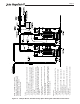

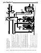


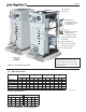

Table Of Contents
- Cover
- TABLE OF CONTENTS
- General Information
- SECTION 2 Venting and Combustion Air
- SECTION 3 Gas supply and Piping
- SECTION 4 Water Flow and Headloss Data
- SECTION 5 Boiler Piping
- SECTION 6 Condensate Drain Trap
- SECTION 7 Electrical Connections
- 7.A Installation Warnings
- 7.B Main Power Connections
- 7.C Main Power Data
- 7.D Control Panel Layout
- 7.E Field Connections
- 7.E.1 Power
- 7.E.2 Dry Contacts
- 7.E.3 Temperature Sensors
- 7.E.4 Safety Chain
- 7.E.5 Isolation Valve
- 7.E.6 Heat Demands
- 7.E.7 Analog In and Analog Out
- 7.E.8 Dry Contacts. Run & Alarm
- 7.E.9 RS 485 for Cascade (Lead Lag)
- 7.E.10 RS485 BMS
- 7.F Modbus to BACnet Memory Map (4 pages)
- 7.G WiringDiagram
- 7.H High Voltage Wiring Diagrams (5 pages)
- 7.I Ladder Diagrams (8 pages)
- SECTION 8 Control Operation
- 8.A The Home Screen
- 8.B Login to Lock / Unlock the Display Screen
- 8.C Quick Start
- 8.D Configuration
- 8.E Service Screens
- 8.E.1 Burner
- 8.E.2 Digital I/O ( Input / Output )
- 8.E.3 Analog I/O
- 8.E.4 Screen Settings Timeout
- 8.E.5 History
- 8.E.6 Restart Touchscreen & Recalibrate
- 8.E.7 Factory Reset
- 8.E.8 HMI Model OEM only
- 8.E.9 BIC Model OEM only
- 8.E.10 Both Model. OEM only.
- 8.E.11 About (the Firmware)
- 8.E.12 O2 (Trim Set Point)
- 8.E.13 LMV
- 8.F Messages and USB
- 8.G Active Demands
- SECTION 9 Parameter Tables (3 pages)
- SECTION 10 Initial startupInstructions
- SECTION 11 Maintenance
- SECTION 12 Troubleshooting
- SECTION 13 Replacement Parts
- 13.A Frame and Jacket Assembly, Part Numbers
- 13.B Control Panel Assembly, Part Numbers
- 13.C Blower and Burner Assembly,Part Numbers. ALL Sizes
- 13.D AC Distribution Box Assemblies and Part Numbers
- 13.E Burner Door Part Numbers
- 13.F Waterway Inlet Assembly, Part Numbers
- 13.G Waterway Outlet Assembly, Part Numbers
- 13.H Gas Train Part Numbers
- 13.I Exhaust Manifold Part Numbers

Page 34
Figure 15. Boiler piping with Plate for
instantaneous DHW heating and
Space Heating
5.E DHW Heating
The MagnaTech FT must not be used as a direct
domestic (potable) water heater. It can be connected to
an indirect water heater or heat exchanger to generate
domestic (potable) hot water and the boiler’s controller
includes indirect water heating logic. Examples of
piping arrangements for indirect domestic water heating
can be found in Section 5.D.
Boiler eciency can be maximized by using piping
congurations that return the lowest temperature
possible to the boiler, while still meeting the needs of
the system.
NOTE: This drawing is a schematic representation of a piping
style and is not intended to be used as a working installation
drawing. Local code requirements must be met.
Control:
• No communication required between the Plate(s)
and boiler(s).
• Boiler(s) assumed to operate on outdoor reset with
suitably high temperature 24 / 7 / 365.
• DHW charging pump runs constant to supply
hydronic water.
• A manually adjustable 2-way valve on Plate allows
bypass ow to avoid pump “dead-heading” during
no DHW loads.
• Plate equipped with its own control system,
monitors DHW and incoming temperatures,
modulates its 3-way valve and internal DHW recirc
pump for fast response.
• This system has instant response to DHW to
demand, small foot print and is easily added o any
central boiler plant for local (in the boiler room) or
remotely in the building for DHW production.
• A buer tank may be required to avoid burner
short cycling. Consult factory for guidelines.
• In case of multiple boilers, connect system senso
to the lead boiler.
BMS control:
• Enable/disable boiler via T-T terminals (49, 50) for
space heating.
• To enable/disable boiler for DHW using an
aquastat, use terminals 53 and 54.
• To enable/disable boiler for DHW using a sensor,
use terminals 39 and 40.
• BMS can control ring rate or setpoint via
terminals 55 and 56. (analog input).
• System pump controlled by BMS or The
Touchscreen Control.