
Installation / Operation Instruction Manual
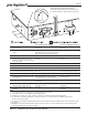
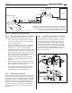

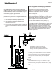
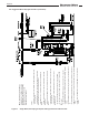


Table Of Contents
- Cover
- TABLE OF CONTENTS
- General Information
- SECTION 2 Venting and Combustion Air
- SECTION 3 Gas supply and Piping
- SECTION 4 Water Flow and Headloss Data
- SECTION 5 Boiler Piping
- SECTION 6 Condensate Drain Trap
- SECTION 7 Electrical Connections
- 7.A Installation Warnings
- 7.B Main Power Connections
- 7.C Main Power Data
- 7.D Control Panel Layout
- 7.E Field Connections
- 7.E.1 Power
- 7.E.2 Dry Contacts
- 7.E.3 Temperature Sensors
- 7.E.4 Safety Chain
- 7.E.5 Isolation Valve
- 7.E.6 Heat Demands
- 7.E.7 Analog In and Analog Out
- 7.E.8 Dry Contacts. Run & Alarm
- 7.E.9 RS 485 for Cascade (Lead Lag)
- 7.E.10 RS485 BMS
- 7.F Modbus to BACnet Memory Map (4 pages)
- 7.G WiringDiagram
- 7.H High Voltage Wiring Diagrams (5 pages)
- 7.I Ladder Diagrams (8 pages)
- SECTION 8 Control Operation
- 8.A The Home Screen
- 8.B Login to Lock / Unlock the Display Screen
- 8.C Quick Start
- 8.D Configuration
- 8.E Service Screens
- 8.E.1 Burner
- 8.E.2 Digital I/O ( Input / Output )
- 8.E.3 Analog I/O
- 8.E.4 Screen Settings Timeout
- 8.E.5 History
- 8.E.6 Restart Touchscreen & Recalibrate
- 8.E.7 Factory Reset
- 8.E.8 HMI Model OEM only
- 8.E.9 BIC Model OEM only
- 8.E.10 Both Model. OEM only.
- 8.E.11 About (the Firmware)
- 8.E.12 O2 (Trim Set Point)
- 8.E.13 LMV
- 8.F Messages and USB
- 8.G Active Demands
- SECTION 9 Parameter Tables (3 pages)
- SECTION 10 Initial startupInstructions
- SECTION 11 Maintenance
- SECTION 12 Troubleshooting
- SECTION 13 Replacement Parts
- 13.A Frame and Jacket Assembly, Part Numbers
- 13.B Control Panel Assembly, Part Numbers
- 13.C Blower and Burner Assembly,Part Numbers. ALL Sizes
- 13.D AC Distribution Box Assemblies and Part Numbers
- 13.E Burner Door Part Numbers
- 13.F Waterway Inlet Assembly, Part Numbers
- 13.G Waterway Outlet Assembly, Part Numbers
- 13.H Gas Train Part Numbers
- 13.I Exhaust Manifold Part Numbers

Page 22
2.D.2 Side-wall Combustion Air Terminal
Consider the following when installing the terminal.
1. Do not locate the air inlet terminal near a source
of corrosive chemical fumes (e.g., cleaning uid,
chlorine compounds, etc.).
2. Locate the terminal so that it will not be subject to
damage by accident or vandalism. It must be at
least 7 feet ( 2.1 m) above a public walkway.
3. Locate the combustion air terminal so that it cannot
be blocked by snow. The National Fuel Gas Code
requires that it be at least 12 inches (30 cm) above
grade, but the installer may determine it should be
higher, depending upon local conditions.
4. If the unit is side-wall vented to the same wall,
use Figure 6 to determine the proper mounting
locations.
5. Multiple vent kits should be installed such that the
horizontal distance between outlet group and inlet
group is 84” (213 cm). (See Figure 6)
6. The vent outlet must be at least 12” above the top
of the air inlet, and must be at least 84” (213 cm)
horizontally from the air inlet. (See Figure 6).
2.D.4 Vertical Combustion Air Terminal
When combustion air is taken from the roof, a eld-
supplied rain cap or an elbow arrangement must be
used to prevent entry of rain water. The opening on
the end of the terminal must be at least 12” (30 cm)
above the point at which it penetrates the roof, and
high enough above the roof line to prevent blockage
from snow. When the vent terminates on the roof, the
combustion air must terminate at least 12” (30 cm)
below the vent terminal.
2.D.3 Vertical Vent Terminal
When the unit is vented through the roof, the vent must
extend at least 3 feet (0.9 m) above the point at which it
penetrates the roof. It must extend at least 2 feet (0.6 m)
higher than any portion of a building within a horizontal
distance of 10 feet (3.0 m), and high enough above
the roof line to prevent blockage from snow. When the
combustion air is taken from the roof, the combustion
air must terminate at least 12” (30 cm) below the vent
terminal.
84”
2” Min. (Typ)
Multiple Vents
Window
2” Min. (Typ)
Multiple Air Intakes
Above expected snow line
213
36”
90
12”
OUTLET
INLET
12”
Figure 6. Sidewall Vent and Air Terminals
Terminals must be placed such that they are a Minimum of 12” above the
expected snow line. Local codes may have more specic requirements
and must be consulted. Refer to the NFPA 54 National Fuel Gas Code
and your local codes for all required clearances for venting.
Figure 7. Combustion Air and Vent Through Roof
*
*
*
*
*
*
Vent Cap
or
Screen
*In Canada, refer to CAN/CSA B149.1