
Installation / Operation Instruction Manual
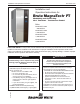

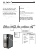


Table Of Contents
- Cover
- TABLE OF CONTENTS
- General Information
- SECTION 2 Venting and Combustion Air
- SECTION 3 Gas supply and Piping
- SECTION 4 Water Flow and Headloss Data
- SECTION 5 Boiler Piping
- SECTION 6 Condensate Drain Trap
- SECTION 7 Electrical Connections
- 7.A Installation Warnings
- 7.B Main Power Connections
- 7.C Main Power Data
- 7.D Control Panel Layout
- 7.E Field Connections
- 7.E.1 Power
- 7.E.2 Dry Contacts
- 7.E.3 Temperature Sensors
- 7.E.4 Safety Chain
- 7.E.5 Isolation Valve
- 7.E.6 Heat Demands
- 7.E.7 Analog In and Analog Out
- 7.E.8 Dry Contacts. Run & Alarm
- 7.E.9 RS 485 for Cascade (Lead Lag)
- 7.E.10 RS485 BMS
- 7.F Modbus to BACnet Memory Map (4 pages)
- 7.G WiringDiagram
- 7.H High Voltage Wiring Diagrams (5 pages)
- 7.I Ladder Diagrams (8 pages)
- SECTION 8 Control Operation
- 8.A The Home Screen
- 8.B Login to Lock / Unlock the Display Screen
- 8.C Quick Start
- 8.D Configuration
- 8.E Service Screens
- 8.E.1 Burner
- 8.E.2 Digital I/O ( Input / Output )
- 8.E.3 Analog I/O
- 8.E.4 Screen Settings Timeout
- 8.E.5 History
- 8.E.6 Restart Touchscreen & Recalibrate
- 8.E.7 Factory Reset
- 8.E.8 HMI Model OEM only
- 8.E.9 BIC Model OEM only
- 8.E.10 Both Model. OEM only.
- 8.E.11 About (the Firmware)
- 8.E.12 O2 (Trim Set Point)
- 8.E.13 LMV
- 8.F Messages and USB
- 8.G Active Demands
- SECTION 9 Parameter Tables (3 pages)
- SECTION 10 Initial startupInstructions
- SECTION 11 Maintenance
- SECTION 12 Troubleshooting
- SECTION 13 Replacement Parts
- 13.A Frame and Jacket Assembly, Part Numbers
- 13.B Control Panel Assembly, Part Numbers
- 13.C Blower and Burner Assembly,Part Numbers. ALL Sizes
- 13.D AC Distribution Box Assemblies and Part Numbers
- 13.E Burner Door Part Numbers
- 13.F Waterway Inlet Assembly, Part Numbers
- 13.G Waterway Outlet Assembly, Part Numbers
- 13.H Gas Train Part Numbers
- 13.I Exhaust Manifold Part Numbers

i
TABLE OF CONTENTS
SECTION 1 General Information
1.A Introduction ............................................... 5
1.B Model Identication .................................. 5
1.C Warranty .................................................... 5
1.D Safety Notes.............................................. 6
1.E Venting Dimensions & Sizing .................... 8
1.F Dimensions ............................................... 8
1.G Unit Overview .......................................... 10
1.H Gas Train Components ........................... 11
1.I Unpacking and the Install Kit................... 12
1.J Locating the Unit ..................................... 12
1.K Clearances .............................................. 13
SECTION 2 Venting and Combustion Air
2.A General Venting Information ................... 14
2.B Vent and Air Pipe Material ....................... 14
2.B.1 Venting Reqs Unique to Canada ............. 14
2.B.1.a Flue Gas Sampling Port - ........................ 14
2.B.1.b Exhaust Vent Terminal - .......................... 15
2.C Vent and Air Pipe Sizing .......................... 16
2.C.1 Category lV Vent Sizes ........................... 17
2.C.2 Category II Vent Sizes............................. 17
2.C.3 Common Venting..................................... 17
2.C.4 Common Vent Test .................................. 18
2.C.5 Combustion Air ........................................ 19
2.C.5.a Combustion Air From Room .................... 19
2.C.5.b Ducted Combustion Air ........................... 20
2.D Locating the Vent /Comb Air Terminals ... 20
2.D.1 Side-wall Vent Terminal ........................... 20
2.D.2 Side-wall Combustion Air Terminal .......... 22
2.D.3 Vertical Vent Terminal .............................. 22
2.D.4 Vertical Combustion Air Terminal ............ 22
2.E Outdoor Installation ................................. 23
2.F Installations in the Massachusetts .......... 23
SECTION 3 Gas supply and Piping
3.A Gas Supply and Piping............................ 24
3.B Gas Pipe Sizing....................................... 24
SECTION 4 Water Flow and Headloss Data
4.A General Water Flow Information ............. 25
4.B Water Flow & Headloss Data .................. 25
SECTION 5 Boiler Piping
5.A Water Connections .................................. 26
5.B Cold Water Make-Up ............................... 26
5.C Freeze Protection .................................... 26
5.D Suggested Boiler Piping Schematics . 27-34
5.E Water Heating ......................................... 34
SECTION 6 Condensate Drain Trap
6.A Condensate Trap Install Instructions ....... 37
SECTION 7 Electrical Connections
7.A Installation Warnings ............................... 38
7.B Main Power Connections ........................ 39
7.C Main Power Data..................................... 40
7.D Control Panel Layout............................... 40
7.E Field Connections .................................. 40
7.E.1 Power ...................................................... 40
7.E.2 Dry Contacts ........................................... 40
7.E.3 Temperature Sensors .............................. 41
7.E.4 Safety Chain............................................ 41
7.E.5 Isolation Valve ......................................... 42
7.E.6 Heat Demands ........................................ 42
7.E.7 Analog In and Analog Out ....................... 42
7.E.8 Dry Contacts. Run & Alarm ..................... 42
7.E.9 RS 485 for Cascade (Lead Lag) ............ 42
7.E.10 RS485 BMS ............................................ 43
7.F Modbus to BACnet Memory Map ............ 44
7.G Wiring Diagram ....................................... 48
7.H High Voltage Wiring Diagrams ...........50-53
7.I Ladder Diagrams................................54-61
SECTION 8 Control Operation
8.A The Home Screen ............................. 62
8.A.1 Home Screen Active Icons ...................... 62
8.A.2 Keypad Operations ................................. 63
8.B Login to Lock / Unlock the Screen . 64
8.C Quick Start ...................................... 65
8.C.1 CH (Central Heat) ................................. 65
8.C.1.a CH1 (Central Heat, One) 1..................... 66
8.C.1.b CH2 (Central Heat, Two) 2 ..................... 66
8.C.2 DHW (Domestic Hot Water) .................. 66
8.C.3 Outdoor Reset ........................................ 67
8.C.4 Warm Weather Shut Down .................... 67
8.C.5 Anti-Short Cycle ..................................... 68
8.C.6 Time & Date ........................................... 68