
Installation / Operation Instruction Manual

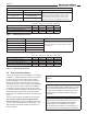
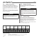
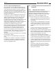
Table Of Contents
- Cover
- TABLE OF CONTENTS
- General Information
- SECTION 2 Venting and Combustion Air
- SECTION 3 Gas supply and Piping
- SECTION 4 Water Flow and Headloss Data
- SECTION 5 Boiler Piping
- SECTION 6 Condensate Drain Trap
- SECTION 7 Electrical Connections
- 7.A Installation Warnings
- 7.B Main Power Connections
- 7.C Main Power Data
- 7.D Control Panel Layout
- 7.E Field Connections
- 7.E.1 Power
- 7.E.2 Dry Contacts
- 7.E.3 Temperature Sensors
- 7.E.4 Safety Chain
- 7.E.5 Isolation Valve
- 7.E.6 Heat Demands
- 7.E.7 Analog In and Analog Out
- 7.E.8 Dry Contacts. Run & Alarm
- 7.E.9 RS 485 for Cascade (Lead Lag)
- 7.E.10 RS485 BMS
- 7.F Modbus to BACnet Memory Map (4 pages)
- 7.G WiringDiagram
- 7.H High Voltage Wiring Diagrams (5 pages)
- 7.I Ladder Diagrams (8 pages)
- SECTION 8 Control Operation
- 8.A The Home Screen
- 8.B Login to Lock / Unlock the Display Screen
- 8.C Quick Start
- 8.D Configuration
- 8.E Service Screens
- 8.E.1 Burner
- 8.E.2 Digital I/O ( Input / Output )
- 8.E.3 Analog I/O
- 8.E.4 Screen Settings Timeout
- 8.E.5 History
- 8.E.6 Restart Touchscreen & Recalibrate
- 8.E.7 Factory Reset
- 8.E.8 HMI Model OEM only
- 8.E.9 BIC Model OEM only
- 8.E.10 Both Model. OEM only.
- 8.E.11 About (the Firmware)
- 8.E.12 O2 (Trim Set Point)
- 8.E.13 LMV
- 8.F Messages and USB
- 8.G Active Demands
- SECTION 9 Parameter Tables (3 pages)
- SECTION 10 Initial startupInstructions
- SECTION 11 Maintenance
- SECTION 12 Troubleshooting
- SECTION 13 Replacement Parts
- 13.A Frame and Jacket Assembly, Part Numbers
- 13.B Control Panel Assembly, Part Numbers
- 13.C Blower and Burner Assembly,Part Numbers. ALL Sizes
- 13.D AC Distribution Box Assemblies and Part Numbers
- 13.E Burner Door Part Numbers
- 13.F Waterway Inlet Assembly, Part Numbers
- 13.G Waterway Outlet Assembly, Part Numbers
- 13.H Gas Train Part Numbers
- 13.I Exhaust Manifold Part Numbers

Page 17
2.C.1 Category lV Vent Sizes
Positive pressure vent systems may be either
horizontally or vertically vented. The vent pipe used
must be suitable for positive pressure. Table 10 shows
the pipe size and allowable maximum equivalent of
piping allowed for both air and vent in a Category lV
system.
The forced draft combustion air blower in the unit has
sucient power to vent properly when the guidelines in
Section 1.E are followed.
WARNING
Cat lV venting must be installed with appropriate
condensate traps and using only specic
manufacturers, models and materials as outlined in
this manual.
WARNING
Cat ll venting must be installed such that draft must
always remain between -0.1” and -0.001” at all
ring rates. If pressures outside of this range are
measured, consult a professional venting engineer for
recommendations, such as double-acting barometric
dampers to avoid reduced performance or hazardous
conditions.
2.C.2 Category II Vent Sizes
Non-positive pressure vent systems are generally
vertically terminated. Table 10 gives guidelines for vent
and air pipe sizes.
2.C.3 Common Venting
This unit can be common vented, however, the
common venting must be a professionally designed
and approved system. See Document 1396.pdf
Application Guide for Common Venting (commercial
condensing, available online. See Back Cover for
website.)
Category II and IV units are never permitted to share
a vent with any Category 1 units.
Venting
Information
inches cm inches cm ft* m inches cm ft* m inches cm
1000 6 15 6 15 100 30.5 6 15 100 30.5 12 30
1500 8 20 8 20 100 30.5 8 20 100 30.5 14 36
2000 8 20 8 20 100 30.5 8 20 100 30.5 18 46
3000 10 25 10 25 100 30.5 10 25 100 30.5 22 56
*Equivalent Feet: Equivalent Feet: To calculate maximum equivalent length, measure the linear feet of the pipe
and add 5 feet (1.5m) for each elbow used.
***Category II: Category II pipe size may vary. Draft must remain between -0.1 and -0.001" w.c..
Notes:
1. Installations in the U.S. require exhaust vent pipe that is CPVC complying with ANSI/ASTM D1785 F441,
stainless steel complying with UL1738, or polypropylene complying with ULC S636.
2. Installations in Canada require exhaust vent pipe that is certified to ULC S636.
3. Intake (air) pipe must be PVC or CPVC that complies with ANSI/ASTM D1785 F441, ABS that complies with
ANSI/ASTM D1527, stainless steel, or galvanized material.
Vent / Air
Connector Size
Model
Maximum
Ducted Air Pipe
Length
Air Pipe Size
Typical
Category II Vent
Pipe Size***
Maximum
Category IV
Vent Pipe
Length
Category IV
Vent Pipe Size
Table 10. Vent Sizing