
Installation / Operation Instruction Manual
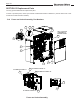
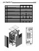
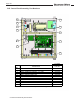
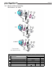

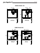
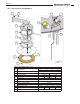
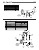
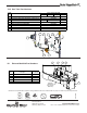
Table Of Contents
- Cover
- TABLE OF CONTENTS
- General Information
- SECTION 2 Venting and Combustion Air
- SECTION 3 Gas supply and Piping
- SECTION 4 Water Flow and Headloss Data
- SECTION 5 Boiler Piping
- SECTION 6 Condensate Drain Trap
- SECTION 7 Electrical Connections
- 7.A Installation Warnings
- 7.B Main Power Connections
- 7.C Main Power Data
- 7.D Control Panel Layout
- 7.E Field Connections
- 7.E.1 Power
- 7.E.2 Dry Contacts
- 7.E.3 Temperature Sensors
- 7.E.4 Safety Chain
- 7.E.5 Isolation Valve
- 7.E.6 Heat Demands
- 7.E.7 Analog In and Analog Out
- 7.E.8 Dry Contacts. Run & Alarm
- 7.E.9 RS 485 for Cascade (Lead Lag)
- 7.E.10 RS485 BMS
- 7.F Modbus to BACnet Memory Map (4 pages)
- 7.G WiringDiagram
- 7.H High Voltage Wiring Diagrams (5 pages)
- 7.I Ladder Diagrams (8 pages)
- SECTION 8 Control Operation
- 8.A The Home Screen
- 8.B Login to Lock / Unlock the Display Screen
- 8.C Quick Start
- 8.D Configuration
- 8.E Service Screens
- 8.E.1 Burner
- 8.E.2 Digital I/O ( Input / Output )
- 8.E.3 Analog I/O
- 8.E.4 Screen Settings Timeout
- 8.E.5 History
- 8.E.6 Restart Touchscreen & Recalibrate
- 8.E.7 Factory Reset
- 8.E.8 HMI Model OEM only
- 8.E.9 BIC Model OEM only
- 8.E.10 Both Model. OEM only.
- 8.E.11 About (the Firmware)
- 8.E.12 O2 (Trim Set Point)
- 8.E.13 LMV
- 8.F Messages and USB
- 8.G Active Demands
- SECTION 9 Parameter Tables (3 pages)
- SECTION 10 Initial startupInstructions
- SECTION 11 Maintenance
- SECTION 12 Troubleshooting
- SECTION 13 Replacement Parts
- 13.A Frame and Jacket Assembly, Part Numbers
- 13.B Control Panel Assembly, Part Numbers
- 13.C Blower and Burner Assembly,Part Numbers. ALL Sizes
- 13.D AC Distribution Box Assemblies and Part Numbers
- 13.E Burner Door Part Numbers
- 13.F Waterway Inlet Assembly, Part Numbers
- 13.G Waterway Outlet Assembly, Part Numbers
- 13.H Gas Train Part Numbers
- 13.I Exhaust Manifold Part Numbers

Color
The AHRI Certified™ mark is designed to be reproduced in one color — either blue or black, and is self-
contained. Artwork is provided for your use in various file formats. DO NOT ALTER OR ADD TO the file provided.
Select the appropriate file for use based on the application samples demonstrated in this manual. If in doubt,
please contact AHRI’s Certification Program Administrator at 703.524.8800, ext. 345 for more information.
Product Labels
PMS 300, C=100, M=42, Y=0, K=0, R=0, G=101, B=189,
HTML: #0065BD, or Black.
Generic Marketing Application
PMS 300, C=100, M=42, Y=0, K=0, R=0, G=101, B=189, HTML: #0065BD
or Black.
Component Labels
Labels for components within units are available in Black
and Blue and can be ordered by contacting AHRI’s Certifi-
cation Program Administrator at 703.524.8800, ext. 345
If the mark MUST reverse out of a dark background use the PMS® 300 mark, or the
black mark. All marks have a white outline.
If the mark MUST reverse out of a dark background use
the PMS® 300 mark, or the black mark. All marks have a
white outline.
CMYK, RGB and HTML color formulas are matched using PANTONE® color formulas from
the Color Bridge® coated color guide. Formulas may vary in dierent programs.
Dimensions and specications subject to change without notice in accordance with our policy of continuous product improvement.
H
13.H Gas Train Part Numbers
5
6
7
1
2
3
4
8
1.0 1.5 2.0 3.0
1
VALVE-ACTUATOR ASSY, GAS, VA SERIES, VKG
V2025600
2
ACTUATOR, ELECTRO-HYDRAULIC, SKP25.011U1
3
BODY, VALVE, GAS
V2015900 V2025300
4
VALVE, GAS, SOLENOID, NC SAFETY SHUTOFF
V2026200
5
SWITCH, HIGH GAS PRESSURE
6
SWITCH, LOW GAS PRESSURE
7
TUBE ASSY, SENSING
10T6003 15T6003 20T6003 30T6003
8 TEST VALVE, MANUAL
GAS TRAIN PARTS, CFT 1.0 - 3.0
R2004000
R2004100
W2000300
V2025400
V2025200
V2026400
PART NO./BOILER SIZEITEM
NO.
DESCRIPTION
V2025500
5
6
7
1
2
3
4
8
1.0 1.5 2.0 3.0
1
VALVE-ACTUATOR ASSY, GAS, VA SERIES, VKG
V2025600
2
ACTUATOR, ELECTRO-HYDRAULIC, SKP25.011U1
3
BODY, VALVE, GAS
V2015900 V2025300
4
VALVE, GAS, SOLENOID, NC SAFETY SHUTOFF
V2026200
5
SWITCH, HIGH GAS PRESSURE
6
SWITCH, LOW GAS PRESSURE
7
TUBE ASSY, SENSING
10T6003 15T6003 20T6003 30T6003
8 TEST VALVE, MANUAL
GAS TRAIN PARTS, CFT 1.0 - 3.0
R2004000
R2004100
W2000300
V2025400
V2025200
V2026400
PART NO./BOILER SIZEITEM
NO.
DESCRIPTION
V2025500
13.I Exhaust Manifold Part Numbers
Exhaust Manifold Part Numbers
32 41
Weldment)
EXHAUST
MANIFOLD
(Part of Boiler
5
1 Adapter, 1/4 Barb ~1/4 NPT, SST P2089300
2 Plug, 3/8" NPT, SST P2134000
3
Sensor, O
2
E2376700
4 Sensor, Stack E2400300
5 Cover, Sensor, Exhaust Manifold 15T3027
Part NumberItem # Description
Exhaust Manifold Part Numbers
32 41
Weldment)
EXHAUST
MANIFOLD
(Part of Boiler
5
1 Adapter, 1/4 Barb ~1/4 NPT, SST P2089300
2 Plug, 3/8" NPT, SST P2134000
3
Sensor, O
2
E2376700
4 Sensor, Stack E2400300
5 Cover, Sensor, Exhaust Manifold 15T3027
Part NumberItem # Description
H2407800-
200 Lafayette St.
Middleville, MI 49333
Warranty: (800) 531-2111
www.BradfordWhite.com
Litho in U.S.A. © Bradford White 20-13 Document 1470-BW