
Installation / Operation Instruction Manual
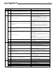

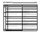
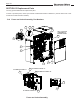
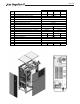
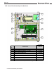
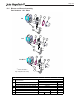

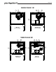
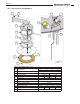
Table Of Contents
- Cover
- TABLE OF CONTENTS
- General Information
- SECTION 2 Venting and Combustion Air
- SECTION 3 Gas supply and Piping
- SECTION 4 Water Flow and Headloss Data
- SECTION 5 Boiler Piping
- SECTION 6 Condensate Drain Trap
- SECTION 7 Electrical Connections
- 7.A Installation Warnings
- 7.B Main Power Connections
- 7.C Main Power Data
- 7.D Control Panel Layout
- 7.E Field Connections
- 7.E.1 Power
- 7.E.2 Dry Contacts
- 7.E.3 Temperature Sensors
- 7.E.4 Safety Chain
- 7.E.5 Isolation Valve
- 7.E.6 Heat Demands
- 7.E.7 Analog In and Analog Out
- 7.E.8 Dry Contacts. Run & Alarm
- 7.E.9 RS 485 for Cascade (Lead Lag)
- 7.E.10 RS485 BMS
- 7.F Modbus to BACnet Memory Map (4 pages)
- 7.G WiringDiagram
- 7.H High Voltage Wiring Diagrams (5 pages)
- 7.I Ladder Diagrams (8 pages)
- SECTION 8 Control Operation
- 8.A The Home Screen
- 8.B Login to Lock / Unlock the Display Screen
- 8.C Quick Start
- 8.D Configuration
- 8.E Service Screens
- 8.E.1 Burner
- 8.E.2 Digital I/O ( Input / Output )
- 8.E.3 Analog I/O
- 8.E.4 Screen Settings Timeout
- 8.E.5 History
- 8.E.6 Restart Touchscreen & Recalibrate
- 8.E.7 Factory Reset
- 8.E.8 HMI Model OEM only
- 8.E.9 BIC Model OEM only
- 8.E.10 Both Model. OEM only.
- 8.E.11 About (the Firmware)
- 8.E.12 O2 (Trim Set Point)
- 8.E.13 LMV
- 8.F Messages and USB
- 8.G Active Demands
- SECTION 9 Parameter Tables (3 pages)
- SECTION 10 Initial startupInstructions
- SECTION 11 Maintenance
- SECTION 12 Troubleshooting
- SECTION 13 Replacement Parts
- 13.A Frame and Jacket Assembly, Part Numbers
- 13.B Control Panel Assembly, Part Numbers
- 13.C Blower and Burner Assembly,Part Numbers. ALL Sizes
- 13.D AC Distribution Box Assemblies and Part Numbers
- 13.E Burner Door Part Numbers
- 13.F Waterway Inlet Assembly, Part Numbers
- 13.G Waterway Outlet Assembly, Part Numbers
- 13.H Gas Train Part Numbers
- 13.I Exhaust Manifold Part Numbers

Page 127
13.C Blower and Burner Assembly,
Part Numbers. ALL Sizes
3
5
1.0 & 1.5
21
4
*
3
4
5
2.0
1
2
*
3
5
3.0
4
1
2
*
Blower Gas-Air Mixer Part Numbers
* = Blower Identified in
High Voltage Box Parts Listing
1.0 1.5 2.0 3.0
O-RING, OUTLET, ACTUATOR
300S5039
GASKET, OUTLET, ACTUATOR
-
2
VALVE-ACTUATOR ASSY, GAS, SIEMENS
V2027900
O-RING, INLET, ACTUATOR
-
GASKET, INLET, ACTUATOR
S2125300
4
INTAKE WELDMENT, AIR
20N5121 30T5121
5 BRACKET, INDEXING, BLOWER 10T2001 15T2001 20T2001 30T2001
Blower & Air-Gas Mixer, CFT 1.0 - 3.0
PART NO./BOILER SIZEITEM
NO.
DESCRIPTION
15T5121
1
3
-
20N5095
V2028300
S2135700
-