
Installation / Operation Instruction Manual
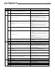

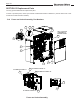
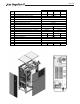
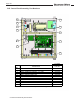
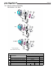

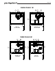
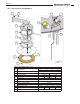
Table Of Contents
- Cover
- TABLE OF CONTENTS
- General Information
- SECTION 2 Venting and Combustion Air
- SECTION 3 Gas supply and Piping
- SECTION 4 Water Flow and Headloss Data
- SECTION 5 Boiler Piping
- SECTION 6 Condensate Drain Trap
- SECTION 7 Electrical Connections
- 7.A Installation Warnings
- 7.B Main Power Connections
- 7.C Main Power Data
- 7.D Control Panel Layout
- 7.E Field Connections
- 7.E.1 Power
- 7.E.2 Dry Contacts
- 7.E.3 Temperature Sensors
- 7.E.4 Safety Chain
- 7.E.5 Isolation Valve
- 7.E.6 Heat Demands
- 7.E.7 Analog In and Analog Out
- 7.E.8 Dry Contacts. Run & Alarm
- 7.E.9 RS 485 for Cascade (Lead Lag)
- 7.E.10 RS485 BMS
- 7.F Modbus to BACnet Memory Map (4 pages)
- 7.G WiringDiagram
- 7.H High Voltage Wiring Diagrams (5 pages)
- 7.I Ladder Diagrams (8 pages)
- SECTION 8 Control Operation
- 8.A The Home Screen
- 8.B Login to Lock / Unlock the Display Screen
- 8.C Quick Start
- 8.D Configuration
- 8.E Service Screens
- 8.E.1 Burner
- 8.E.2 Digital I/O ( Input / Output )
- 8.E.3 Analog I/O
- 8.E.4 Screen Settings Timeout
- 8.E.5 History
- 8.E.6 Restart Touchscreen & Recalibrate
- 8.E.7 Factory Reset
- 8.E.8 HMI Model OEM only
- 8.E.9 BIC Model OEM only
- 8.E.10 Both Model. OEM only.
- 8.E.11 About (the Firmware)
- 8.E.12 O2 (Trim Set Point)
- 8.E.13 LMV
- 8.F Messages and USB
- 8.G Active Demands
- SECTION 9 Parameter Tables (3 pages)
- SECTION 10 Initial startupInstructions
- SECTION 11 Maintenance
- SECTION 12 Troubleshooting
- SECTION 13 Replacement Parts
- 13.A Frame and Jacket Assembly, Part Numbers
- 13.B Control Panel Assembly, Part Numbers
- 13.C Blower and Burner Assembly,Part Numbers. ALL Sizes
- 13.D AC Distribution Box Assemblies and Part Numbers
- 13.E Burner Door Part Numbers
- 13.F Waterway Inlet Assembly, Part Numbers
- 13.G Waterway Outlet Assembly, Part Numbers
- 13.H Gas Train Part Numbers
- 13.I Exhaust Manifold Part Numbers

Page 121
Error
Code
Diag.
Code
Meaning for the LMV3 Corrective Action
Note: Diagnostic codes are additive. If a diagnostic code appears that is not on this list, it is a combination of multiple diagnostic codes.
1 Timeout of standardization (VSD ramp down time too long)
Standardization timed out because the VSD took too long to ramp down
at the end of the standardization. Either decrease the ramp down time in
the VSD or increase the setting of parameter 523.
2 Storage of standardized speed not successful
Press the info button with any other button to cause a manual lockout,
then reset the fault and attempt to standardize again.
3 Line interruption speed sensor
No pulses from the speed sensor were detected during standardization.
1) Verify that the motor is rotating.
2) Check the wiring between the speed sensor and the LMV3.
3) Check and / or adjust the gap between the speed wheel and the
sensor. The gap should be about 1/16" (2mm), or about two turns away
from the speed wheel.
4
Speed variation / VSD ramp up time too long / speed below minimum limit
for standardization
A stable speed was not reached after ramping up the VSD, so a
standardized speed could not be determined.
1) Either decrease the ramp up time in the VSD or increase the setting of
parameter 522.
2) Check for filters, damping, or delays on the input signal to the VSD.
The VSD should respond to the input signal in a linear fashion.
3) Ensure that the VSD and LMV3 are configured for the same analog
signal (0-10 VDC).
5 Wrong direction of rotation
1) Check to see if the motor's direction of rotation is correct. Reverse if
necesssary.
2) Check to see if the arrow on the speed wheel points in the correct
direction of rotation. Reverse if necessary.
6 Unplausible sensor signals
1) Check the setting of parameter 643 and ensure it is set correctly. For
VSD + 3-phase motor, this should be a 0. For most brushless DC blowers,
this should be a 1.
2) Check and / or adjust the gap between the speed wheel and the
sensor. The gap should be about 1/16" (2mm), or about two turns away
from the speed wheel.
3) Check the wiring of the speed sensor. Ensure the reference ground is
properly connected.
4) Ensure that other metal parts besides the speed wheel are not being
picked up by the sensor when the motor rotates.
7 Invalid standardized speed
The standardized speed measured does not lie in the permissible range
(650-14,000 RPM).
15 Speed deviation µC1 + µC2 Reset the fault and repeat the standardization.
20 Wrong phase of phase manager Standardization must be performed in standby (phase 12).
21 Safety loop / burner flange open
Fix any conditions causing a limit in the safety loop / burner flange circuit
to be open, then attempt to standardize again.
22 Air actuator not referenced
Typically caused by trying to standardize while the air actuator is currently
referencing. Wait for the actuator to finish referencing and try to
standardize again. If the fault persists, see error code 85, diagnostic code
1 for additional troubleshooting.
23 VSD deactivated
The VSD must be activated before standardization can be performed. Set
parameter 542 to a 1 and attempt to standardize again.
24 No valid operation mode
A fuel train must be selected before standardization can be performed.
Select a fuel train via parameter 201 (fuel 0) or 301 (fuel 1), then attempt
to standardize again.
25 Pneumatic air-fuel ratio control
Standardization cannot be performed when using a pneumatic fuel train.
Select a different fuel train via parameter 201 (fuel 0) or 301 (fuel 1), then
attempt to standardize again.
128 Running command with no preceding standardization
A call for heat was received and the VSD is activated (parameter 542 = 1),
but no standardization has been performed. Perform a standardization
by setting parameter 641 to a 1 while in standby phase 12, or deactivate
the VSD by setting parameter 542 to 0.
255 No standardized speed available Perform a standardization via parameter 641 while in standby (phase 12).
Any # Speed error VSD A VSD speed error occurred. See diagnostics codes for more information.
0 Speed error when trim function is active
Increase parameter 662 (neutral zone) and 663 (near zone) or deactivate
VSD trim via parameter 530.
1 Lower control range limitation of control See error code 80, diagnostic code 1.
2 Upper control range limitation of control See error code 80, diagnostic code 2.
4 Interruption via disturbance pulses See error code 81, diagnostic code 1.
8 Curve too steep in terms of ramp speed See error code 84.
82
83
82
82