
Installation / Operation Instruction Manual
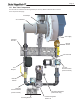
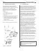

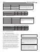
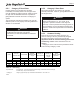
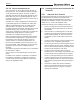
Table Of Contents
- Cover
- TABLE OF CONTENTS
- General Information
- SECTION 2 Venting and Combustion Air
- SECTION 3 Gas supply and Piping
- SECTION 4 Water Flow and Headloss Data
- SECTION 5 Boiler Piping
- SECTION 6 Condensate Drain Trap
- SECTION 7 Electrical Connections
- 7.A Installation Warnings
- 7.B Main Power Connections
- 7.C Main Power Data
- 7.D Control Panel Layout
- 7.E Field Connections
- 7.E.1 Power
- 7.E.2 Dry Contacts
- 7.E.3 Temperature Sensors
- 7.E.4 Safety Chain
- 7.E.5 Isolation Valve
- 7.E.6 Heat Demands
- 7.E.7 Analog In and Analog Out
- 7.E.8 Dry Contacts. Run & Alarm
- 7.E.9 RS 485 for Cascade (Lead Lag)
- 7.E.10 RS485 BMS
- 7.F Modbus to BACnet Memory Map (4 pages)
- 7.G WiringDiagram
- 7.H High Voltage Wiring Diagrams (5 pages)
- 7.I Ladder Diagrams (8 pages)
- SECTION 8 Control Operation
- 8.A The Home Screen
- 8.B Login to Lock / Unlock the Display Screen
- 8.C Quick Start
- 8.D Configuration
- 8.E Service Screens
- 8.E.1 Burner
- 8.E.2 Digital I/O ( Input / Output )
- 8.E.3 Analog I/O
- 8.E.4 Screen Settings Timeout
- 8.E.5 History
- 8.E.6 Restart Touchscreen & Recalibrate
- 8.E.7 Factory Reset
- 8.E.8 HMI Model OEM only
- 8.E.9 BIC Model OEM only
- 8.E.10 Both Model. OEM only.
- 8.E.11 About (the Firmware)
- 8.E.12 O2 (Trim Set Point)
- 8.E.13 LMV
- 8.F Messages and USB
- 8.G Active Demands
- SECTION 9 Parameter Tables (3 pages)
- SECTION 10 Initial startupInstructions
- SECTION 11 Maintenance
- SECTION 12 Troubleshooting
- SECTION 13 Replacement Parts
- 13.A Frame and Jacket Assembly, Part Numbers
- 13.B Control Panel Assembly, Part Numbers
- 13.C Blower and Burner Assembly,Part Numbers. ALL Sizes
- 13.D AC Distribution Box Assemblies and Part Numbers
- 13.E Burner Door Part Numbers
- 13.F Waterway Inlet Assembly, Part Numbers
- 13.G Waterway Outlet Assembly, Part Numbers
- 13.H Gas Train Part Numbers
- 13.I Exhaust Manifold Part Numbers

Page 12
1.I Unpacking and the Install Kit
This unit is shipped in a single crate. Carefully
disassemble the crate and inspect the unit for any
damage during shipping. Included in the crate and yet
outside of the unit is the ‘Installation Kit’ box.
Inspect the contents of the the Installation Kit box,
making sure that all parts are included and not
damaged.
1. Gromet, Nylon.
2. Box containing Outdoor Sensor
3. Box containing System Sensor
4. Tank Sensor
5. Spring Clip (used to hold tank sensor in sensor well)
6. Condensate Trap Assembly (some assembly
required). Instructions are included with the kit or
can be found in SECTION 6 on page 36 of this
Installation Manual.
7. Installation Instructions for Sensors.
NOTE: A condensate neutralizer is NOT included.
1
2
3
4
5
6
7
Figure 2. Installation Kit
1.J Locating the Unit
This unit may be installed indoors or outdoors. If installing
outdoors in a location that may experience freezing
temperatures, precautions must be taken to prevent water
in the heat exchanger and condensate inside and outside
of the boiler from freezing. Damage due to freezing water
or condensate is not covered by the warranty.
Choose a location for the unit which allows clearances on
all sides for maintenance and inspection. See Table 3.
Always install the unit on a rm, level surface. The unit
must be installed on a 4” equipment pad or suitable
blocking so that there is elevation for the condensate trap
and condensate neutralizer (not included). See Figure 16
on page 36 for pad dimensions and condensate trap
position.
The unit should not be located in an area where leakage
of any connections will result in damage to the area
adjacent to the unit, or to lower oors of the structure.
When this type of location is not available, install a
suitable drain pan, adequately drained, under the unit.
This unit is design-certied by CSA-International for
installation on combustible ooring; in basements;
in utility rooms or alcoves. Boilers must never be
installed on carpeting. The location for the unit should
be chosen with regard to the vent pipe lengths and
external plumbing.
The unit shall be installed such that the gas ignition
system components are protected from water (dripping,
spraying, rain, etc.) during operation and service (circulator
replacement, control replacement, etc.).
When vented vertically, the unit must be located as close
as practical to the vertical section of the vent. If the vent
terminal and/or combustion air terminal terminate through
a wall, and there is potential for snow accumulation in
the local area, both terminals should be installed at an
appropriate level above grade or the maximum expected
snow line.
The dimensions and requirements that are shown in
Table 3 must be met when choosing the location for the
unit.
Ensure the location takes into account the maximum
allowable vent length shown in SECTION 2 of this
manual.
NOTE : The unit shall be installed such that the gas
ignition system components are protected from water
(dripping, spraying, rain, etc.) during operation and
service (circulator replacement, control
replacement, etc.).
Clearances
inches cm inches cm
Front 18 46 24 61
Back 11 28 24 61
Left 3 8 12 30
Right 3 8 12 30
Top 24* 61 24* 61
Note: A 4" high equipment pad is required.
This pad must NOT extend more than 3" beyond the boiler base structure at the rear of the boiler.
*24" top clearance is required to service the unit.
Clearance to
Combustibles
Suggested
Service
Clearance