
Installation / Operation Instruction Manual
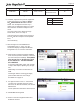
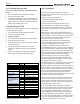
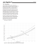
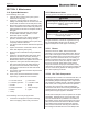
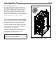
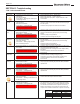
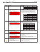
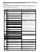
Table Of Contents
- Cover
- TABLE OF CONTENTS
- General Information
- SECTION 2 Venting and Combustion Air
- SECTION 3 Gas supply and Piping
- SECTION 4 Water Flow and Headloss Data
- SECTION 5 Boiler Piping
- SECTION 6 Condensate Drain Trap
- SECTION 7 Electrical Connections
- 7.A Installation Warnings
- 7.B Main Power Connections
- 7.C Main Power Data
- 7.D Control Panel Layout
- 7.E Field Connections
- 7.E.1 Power
- 7.E.2 Dry Contacts
- 7.E.3 Temperature Sensors
- 7.E.4 Safety Chain
- 7.E.5 Isolation Valve
- 7.E.6 Heat Demands
- 7.E.7 Analog In and Analog Out
- 7.E.8 Dry Contacts. Run & Alarm
- 7.E.9 RS 485 for Cascade (Lead Lag)
- 7.E.10 RS485 BMS
- 7.F Modbus to BACnet Memory Map (4 pages)
- 7.G WiringDiagram
- 7.H High Voltage Wiring Diagrams (5 pages)
- 7.I Ladder Diagrams (8 pages)
- SECTION 8 Control Operation
- 8.A The Home Screen
- 8.B Login to Lock / Unlock the Display Screen
- 8.C Quick Start
- 8.D Configuration
- 8.E Service Screens
- 8.E.1 Burner
- 8.E.2 Digital I/O ( Input / Output )
- 8.E.3 Analog I/O
- 8.E.4 Screen Settings Timeout
- 8.E.5 History
- 8.E.6 Restart Touchscreen & Recalibrate
- 8.E.7 Factory Reset
- 8.E.8 HMI Model OEM only
- 8.E.9 BIC Model OEM only
- 8.E.10 Both Model. OEM only.
- 8.E.11 About (the Firmware)
- 8.E.12 O2 (Trim Set Point)
- 8.E.13 LMV
- 8.F Messages and USB
- 8.G Active Demands
- SECTION 9 Parameter Tables (3 pages)
- SECTION 10 Initial startupInstructions
- SECTION 11 Maintenance
- SECTION 12 Troubleshooting
- SECTION 13 Replacement Parts
- 13.A Frame and Jacket Assembly, Part Numbers
- 13.B Control Panel Assembly, Part Numbers
- 13.C Blower and Burner Assembly,Part Numbers. ALL Sizes
- 13.D AC Distribution Box Assemblies and Part Numbers
- 13.E Burner Door Part Numbers
- 13.F Waterway Inlet Assembly, Part Numbers
- 13.G Waterway Outlet Assembly, Part Numbers
- 13.H Gas Train Part Numbers
- 13.I Exhaust Manifold Part Numbers

Page 118
SECTION 12 Troubleshooting
Condition
Information
Corrective Action
Flow Switch
• Insufficient flow at the outlet of the
boiler/heater
• Auto-reset Condition
• Annunciation – “Warning Flow switch open”
on Message Screen
• Faulty boiler/heater pump – replace pump.
• Faulty pump contactor – replace contactor.
• Blown boiler/heater pump fuse – replace fuse F14 on the
control board.
Low Water
Cut Off
• Insufficient water level in the boiler/heater
heat exchanger.
• Manual-reset Condition
• Annunciation – on Navigation Bar
• Reset the LWCO from the reset button on the LWCO module.
• Verify the system is full of water and all air has been purged
from the system.
• Check for loose jumpers if the LWCO is not installed.
Manual
Reset High
Limit
• Outlet water temperature has exceeded the
manual reset high limit setting
• Manual-reset Condition
• Annunciation – on Navigation Bar
• Verify the system is full of water and all air has been purged
from the system.
• Verify the boiler/heater is piped properly into the heating
system.
• Check for proper pump operations.
• Check the manual reset high limit set point.
Auto Reset
High Limit
• Outlet water temperature has exceeded the
auto reset high limit setting
• Auto-reset Condition
• Annunciation – “Warning High limit auto
error” on Message Screen
• Verify the system is full of water and all air has been purged
from the system.
• Verify the boiler/heater is piped properly into the heating
system.
• Check for proper pump operations.
• Check the manual reset high limit set point.
Pressure
Transmitter
• Pressure transmitters are not measuring the
same values.
• Check the wiring connections at transmitters and BIC (x122)
• VCC to Ground should equal 5 Volts.
• Check pressure levels on Analog IN screen. Replace faulty
transmitter.
• Check that pressure sense lines are not kinked or
disconnected.
Pressure
Transmitter
• Pressure not within bounds
• Check that inlet and exhaust ducts are not blocked.
• Check that blower is rotating during pre-purge.
• Check wiring connections at transmitters and BIC (x22).
• Check that pressure sense lines are not kinked or
disconnected.
High Gas
Pressure
• The high gas pressure switch has tripped
• Manual-reset Condition
• Annunciation – on Navigation Bar
• Refer to Section 3 for Gas Supply and Piping information.
• Verify supply and manifold gas pressures satisfy installation
requirements.
Low Gas
Pressure
• The low gas pressure switch has tripped
• Manual-reset Condition
• Annunciation – on Navigation Bar
• Refer to Section 3 for Gas Supply and Piping information.
• Verify supply and manifold gas pressures satisfy installation
requirements.
Condensate
Level
• Condensate trap water level is high
• Auto-reset Condition
• Annunciation – “Warning Condensate level”
on Message screen
• Check condensate trap for proper drainage
• Check condensate trap for stuck level switch
Outlet
Sensor
• Outlet probe is not connected
• Manual-reset Condition
• Annunciation – on Navigation Bar
• Check the sensor and wiring. Repair or replace as needed.
• The outlet probe is a dual element probe with 10K and 20K
thermistors. A quick test is to measure resistance and verify
one resistance is double the other. Replace if necessary.
• Measure the resistance of each element of the sensor and
compare to the resistance table below. Replace if necessary.
Temp (°F)
10K
20K
Resistance (Ω)
Resistance (Ω)
68
12555
25099
86
8025
16057
104
5279
10569
122
3563
7139
Lockout: Low Water Cut Off
Lockout: Man Reset High Limit
Lockout: Air Pressure Drift Error
Lockout: Burner AN Pressure ERR
Lockout: High Gas Pressure
Lockout: Low Gas Pressure
Lockout: Outlet Probe
12.A Lockouts and Errors.