
Installation / Operation Instruction Manual
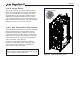
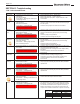
Table Of Contents
- Cover
- TABLE OF CONTENTS
- General Information
- SECTION 2 Venting and Combustion Air
- SECTION 3 Gas supply and Piping
- SECTION 4 Water Flow and Headloss Data
- SECTION 5 Boiler Piping
- SECTION 6 Condensate Drain Trap
- SECTION 7 Electrical Connections
- 7.A Installation Warnings
- 7.B Main Power Connections
- 7.C Main Power Data
- 7.D Control Panel Layout
- 7.E Field Connections
- 7.E.1 Power
- 7.E.2 Dry Contacts
- 7.E.3 Temperature Sensors
- 7.E.4 Safety Chain
- 7.E.5 Isolation Valve
- 7.E.6 Heat Demands
- 7.E.7 Analog In and Analog Out
- 7.E.8 Dry Contacts. Run & Alarm
- 7.E.9 RS 485 for Cascade (Lead Lag)
- 7.E.10 RS485 BMS
- 7.F Modbus to BACnet Memory Map (4 pages)
- 7.G WiringDiagram
- 7.H High Voltage Wiring Diagrams (5 pages)
- 7.I Ladder Diagrams (8 pages)
- SECTION 8 Control Operation
- 8.A The Home Screen
- 8.B Login to Lock / Unlock the Display Screen
- 8.C Quick Start
- 8.D Configuration
- 8.E Service Screens
- 8.E.1 Burner
- 8.E.2 Digital I/O ( Input / Output )
- 8.E.3 Analog I/O
- 8.E.4 Screen Settings Timeout
- 8.E.5 History
- 8.E.6 Restart Touchscreen & Recalibrate
- 8.E.7 Factory Reset
- 8.E.8 HMI Model OEM only
- 8.E.9 BIC Model OEM only
- 8.E.10 Both Model. OEM only.
- 8.E.11 About (the Firmware)
- 8.E.12 O2 (Trim Set Point)
- 8.E.13 LMV
- 8.F Messages and USB
- 8.G Active Demands
- SECTION 9 Parameter Tables (3 pages)
- SECTION 10 Initial startupInstructions
- SECTION 11 Maintenance
- SECTION 12 Troubleshooting
- SECTION 13 Replacement Parts
- 13.A Frame and Jacket Assembly, Part Numbers
- 13.B Control Panel Assembly, Part Numbers
- 13.C Blower and Burner Assembly,Part Numbers. ALL Sizes
- 13.D AC Distribution Box Assemblies and Part Numbers
- 13.E Burner Door Part Numbers
- 13.F Waterway Inlet Assembly, Part Numbers
- 13.G Waterway Outlet Assembly, Part Numbers
- 13.H Gas Train Part Numbers
- 13.I Exhaust Manifold Part Numbers

Page 114
SECTION 11 Maintenance
a. The units controls
b. Automatic gas valve
c. Air lter
d. Pressure switches
e. Blower
f. Pump
g. Flow switch
h. Low water cuto
i. Burner
j. Heat exchanger
k. Ignitor
Do the following once every six (6) months:
1. If a strainer is employed in a pressure reducing
valve or the piping, clean it every six months.
11.A System Maintenance
Do the following once a year:
1. Lubricate all the pumps in the system, per the
instructions on the pump.
2. Inspect the venting system for obstruction or
leakage. Periodically clean the screens in the vent
terminal and combustion air terminal (when used).
3. Remove and inspect the air lter. Clean with soapy
water if needed. Be sure that lter is dry before re-
inserting back into air lter box. Replace air lter if
damaged.
4. Keep the area around the unit clear and free
of combustible materials, gasoline, or other
ammable vapors or liquids.
5. If the unit is not going to be used for extended
periods in locations where freezing normally
occurs, it should be isolated from the system and
completely drained of all water.
6. Low water cutos should be cleaned and inspected
annually.
7. Inspect and clean the condensate collection, oat
switch and disposal system yearly.
8. Ensure that the condensate is being neutralized
properly.
9. Inspect the ue passages and clean them using
brushes or vacuums, if necessary. Sooting in
ue passages indicates improper combustion.
Determine the cause of the problem and correct it.
10. Inspect the vent system and air intake system
and ensure that all joints are sealed properly. If
any joints need to be resealed, follow venting
manufacturer’s instructions to clean and reseal
vent system.
11. The pressure relief valve should be inspected and
tested every year.
12. Once a year, the items listed below should be
inspected by a qualied service technician:
11.B Maintenance Notes
Use only genuine manufacturers replacement parts.
CAUTION
When servicing the controls, label all wires before
disconnecting them. Wiring errors can cause improper
and dangerous operation. Verify proper operation
after servicing.
WARNING
Disconnect all power to the unit before attempting any
service procedures. Contact with electricity can result
in severe injury or death.
The gas and electric controls are engineered for long
life and dependable operation, but the safety of the
equipment depends on their proper functioning.
11.B.1 Burner
Check the burner for debris. Remove the blower
assembly to access the blower adapter plate. Remove
the 4 bolts connecting the blower to the arm. Remove
the blower adapter plate to access the burner. Pull the
burner up and out. Clean the burner, if necessary, by
blowing compressed air from the outside of the burner
into the center of the burner, and wipe the inside of
the burner clean with glass cleaner. A dirty burner
may be an indication of improper combustion or dirty
combustion air. Determine the cause of the problem and
correct it. If the burner gaskets are damaged, replace
them when replacing the burner.
11.B.2 Gas Train Components
The air/gas train consists of an on/o solenoid valve, on/
o pressure regulating valve, fuel modulating damper,
air modulating damper and air/gas mixer. Pipe unions
are included to facilitate removal of the piping assembly,
in the event, that a component needs to be replaced.
In general, the components contain threaded pipe
connections and can be removed using standard gas
plumbing practices. Before removing components, shut
o the power and gas supplies to the boiler.
The air and fuel dampers must be replaced as complete
assemblies. Replacement of only the actuator, in the
event of actuator failure is prohibited. The cables for
the actuator must be disconnected at the main control
panel, X54 and X53 at the Siemens LMV36 controller.
The cables cannot be disconnected at the actuator.
Care must be exercised in removing the cables from
the existing wire bundles and once new dampers are