
Installation / Operation Instruction Manual
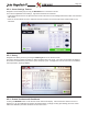
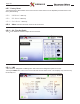
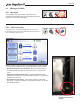
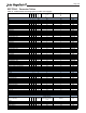
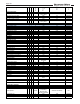
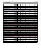
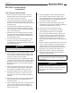

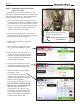
Table Of Contents
- Cover
- TABLE OF CONTENTS
- General Information
- SECTION 2 Venting and Combustion Air
- SECTION 3 Gas supply and Piping
- SECTION 4 Water Flow and Headloss Data
- SECTION 5 Boiler Piping
- SECTION 6 Condensate Drain Trap
- SECTION 7 Electrical Connections
- 7.A Installation Warnings
- 7.B Main Power Connections
- 7.C Main Power Data
- 7.D Control Panel Layout
- 7.E Field Connections
- 7.E.1 Power
- 7.E.2 Dry Contacts
- 7.E.3 Temperature Sensors
- 7.E.4 Safety Chain
- 7.E.5 Isolation Valve
- 7.E.6 Heat Demands
- 7.E.7 Analog In and Analog Out
- 7.E.8 Dry Contacts. Run & Alarm
- 7.E.9 RS 485 for Cascade (Lead Lag)
- 7.E.10 RS485 BMS
- 7.F Modbus to BACnet Memory Map (4 pages)
- 7.G WiringDiagram
- 7.H High Voltage Wiring Diagrams (5 pages)
- 7.I Ladder Diagrams (8 pages)
- SECTION 8 Control Operation
- 8.A The Home Screen
- 8.B Login to Lock / Unlock the Display Screen
- 8.C Quick Start
- 8.D Configuration
- 8.E Service Screens
- 8.E.1 Burner
- 8.E.2 Digital I/O ( Input / Output )
- 8.E.3 Analog I/O
- 8.E.4 Screen Settings Timeout
- 8.E.5 History
- 8.E.6 Restart Touchscreen & Recalibrate
- 8.E.7 Factory Reset
- 8.E.8 HMI Model OEM only
- 8.E.9 BIC Model OEM only
- 8.E.10 Both Model. OEM only.
- 8.E.11 About (the Firmware)
- 8.E.12 O2 (Trim Set Point)
- 8.E.13 LMV
- 8.F Messages and USB
- 8.G Active Demands
- SECTION 9 Parameter Tables (3 pages)
- SECTION 10 Initial startupInstructions
- SECTION 11 Maintenance
- SECTION 12 Troubleshooting
- SECTION 13 Replacement Parts
- 13.A Frame and Jacket Assembly, Part Numbers
- 13.B Control Panel Assembly, Part Numbers
- 13.C Blower and Burner Assembly,Part Numbers. ALL Sizes
- 13.D AC Distribution Box Assemblies and Part Numbers
- 13.E Burner Door Part Numbers
- 13.F Waterway Inlet Assembly, Part Numbers
- 13.G Waterway Outlet Assembly, Part Numbers
- 13.H Gas Train Part Numbers
- 13.I Exhaust Manifold Part Numbers

Page 109
10.B Initial Operation
The initial setup must be checked before the unit is
put into operation. Problems such as failure to start,
rough ignition, strong exhaust odors, etc. can be due
to improper setup. Damage to the boiler resulting from
improper setup is not covered by the limited warranty.
10.B.1 Initial Burner Operation
1. Using this manual, make sure the installation is
complete and in full compliance with the instructions and
all local codes.
2. Determine that the unit and system are lled with
water and all air has been bled from both. Open all
valves.
3. Observe all warnings on the Operating Instructions
label and turn on gas and electrical power to the
unit. It may be neccesary to reset the low pressure
switch.
4. The unit will enter the start sequence. The blower
and pump will energize for pre-purge, then the
ignition sequence will start. After all safety devices
are veried, the gas valve will open.
If ignition doesn’t occur, turn o the unit. Check
that there is proper supply of gas. Wait ve
minutes and start the unit again.
5. If ignition starts normally, leave the unit turned on.
6. After placing the unit into operation, the burner
safety shuto device must be tested:
(a) Close the gas shuto valve with the burner
operating.
(b) The ame will go out, and the blower will continue
to run for the post purge cycle. A few additional
attempts to light will follow including pre-purge,
ignitor on, valve/ame on and post purge. Ignition
will not occur because the gas is turned o. The
ignition control will lockout.
(c) Open the gas shuto valve. Reset the boiler
control by pressing the Reset button on the
control. Restart the unit. The ignition sequence will
start again and the burner will start. The unit will
return to its previous mode of operation.
WARNING
If any odor of gas is detected, or if the gas burner
does not appear to be functioning in a normal
manner, close the main gas shuto valve. Do
not shut o the power switch. Contact your heating
contractor, gas company, or factory representative.
WARNING
Do not use automotive antifreeze. To help prevent
freezing, the manufacturer recommends the use of
inhibited propylene glycol. See 5.C on page 26
WARNING
Improper adjustment may lead to poor combustion
quality, increasing the amount of carbon monoxide
produced. Excess carbon monoxide levels may lead
to personal injury or death.