
Installation / Operation Instruction Manual
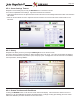
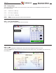
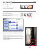
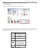
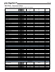
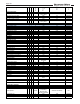
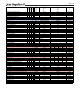

Table Of Contents
- Cover
- TABLE OF CONTENTS
- General Information
- SECTION 2 Venting and Combustion Air
- SECTION 3 Gas supply and Piping
- SECTION 4 Water Flow and Headloss Data
- SECTION 5 Boiler Piping
- SECTION 6 Condensate Drain Trap
- SECTION 7 Electrical Connections
- 7.A Installation Warnings
- 7.B Main Power Connections
- 7.C Main Power Data
- 7.D Control Panel Layout
- 7.E Field Connections
- 7.E.1 Power
- 7.E.2 Dry Contacts
- 7.E.3 Temperature Sensors
- 7.E.4 Safety Chain
- 7.E.5 Isolation Valve
- 7.E.6 Heat Demands
- 7.E.7 Analog In and Analog Out
- 7.E.8 Dry Contacts. Run & Alarm
- 7.E.9 RS 485 for Cascade (Lead Lag)
- 7.E.10 RS485 BMS
- 7.F Modbus to BACnet Memory Map (4 pages)
- 7.G WiringDiagram
- 7.H High Voltage Wiring Diagrams (5 pages)
- 7.I Ladder Diagrams (8 pages)
- SECTION 8 Control Operation
- 8.A The Home Screen
- 8.B Login to Lock / Unlock the Display Screen
- 8.C Quick Start
- 8.D Configuration
- 8.E Service Screens
- 8.E.1 Burner
- 8.E.2 Digital I/O ( Input / Output )
- 8.E.3 Analog I/O
- 8.E.4 Screen Settings Timeout
- 8.E.5 History
- 8.E.6 Restart Touchscreen & Recalibrate
- 8.E.7 Factory Reset
- 8.E.8 HMI Model OEM only
- 8.E.9 BIC Model OEM only
- 8.E.10 Both Model. OEM only.
- 8.E.11 About (the Firmware)
- 8.E.12 O2 (Trim Set Point)
- 8.E.13 LMV
- 8.F Messages and USB
- 8.G Active Demands
- SECTION 9 Parameter Tables (3 pages)
- SECTION 10 Initial startupInstructions
- SECTION 11 Maintenance
- SECTION 12 Troubleshooting
- SECTION 13 Replacement Parts
- 13.A Frame and Jacket Assembly, Part Numbers
- 13.B Control Panel Assembly, Part Numbers
- 13.C Blower and Burner Assembly,Part Numbers. ALL Sizes
- 13.D AC Distribution Box Assemblies and Part Numbers
- 13.E Burner Door Part Numbers
- 13.F Waterway Inlet Assembly, Part Numbers
- 13.G Waterway Outlet Assembly, Part Numbers
- 13.H Gas Train Part Numbers
- 13.I Exhaust Manifold Part Numbers

Page 107
User
Installer
OEM
Factory
Minimum
Maximu
m
Unit
Default
Summer Kick Isolation Valve
x
x
0 600
Seconds
Summer Kick Period
x
x
10 2000
Minute
Cycle Time
x
x
1 240
Seconds
Conversion Unit
x x Celsius Fahrenheit
°F/C
Protocol
x x N/A Modbus / BACnet N/A
Baudrate
x
x
9600 76800
Bits/Second
A
ddress
x
x
0 255 N/A
Device Model Name
x
x
NA NA N/A
Device Object Name
x
x
NA NA N/A
Object Instance
x
x
0 4194303 N/A
Timeout
x
x
0 300
Seconds
Isolation Valv
e
Enable/Disable
x
x
Disable Enable
N/A
Open Time Dela
y
x
x
70 250
Seconds
Close Time Dela
y
x
x
70 250
Seconds
Manual Open
x
x
Closed O
p
en
N/A
Manual Close
x
x
O
p
en Closed
N/A
Min. # of Open Valves
x
x
18
N/A
Burne
r
Burner Enable/Disable
x
x
Disable Enable N/A
Light Timeou
t
x
x
x
60 3600
Seconds
A
utoLock Timeout
x
x
x
60 3600
Seconds
Pressure
1.0 1.5 2.0 3.0
a
x
-32768 32767 600 600 600 700
N/A
b
x
-32768 32767 -5000 -7500 -7500 -5000
N/A
c
x
-32768 32767 10000 8000 12000 12000
N/A
Maximum Allowable Drif
t
x
1 10
%
Validation Time
x
0 20
Seconds
Min Drift Value
x
0 40
0.01" W.C.
Hysteresis
x
0 402
0.01" W.C.
Pressure - Fan Limits
1.0 1.5 2.0 3.0
No Fan Limi
t
x
0 402
0.01" W.C.
Maximum Fan Limit Lowe
r
x
0 402 75 75 75 75
0.01" W.C.
Maximum Fan Limit Highe
r
x
0 402 350 350 350 350
0.01" W.C.
Slope
x
0 2000
N/A
Offset
x
-1000 1000
N/A
P1 Voltage
x
0 5000
mV
P2 Voltage
x
0 5000
mV
P1 Pressure
x
0 803
0.01" W.C.
P2 Pressure
x
0 803
0.01" W.C.
Enable/Disable (Config - Misc Screen Only
)
x
x
Disable Enable N/A
Trim Slope (used to be Trim Value
)
x
-150 250 0.10%
Trim Offset
x
-1000 1000 u
A
Trim Set Point
x
x
20 50
0.10%
Proportional Gain
x
-32768 32767
N/A
Integral Time
x
-32768 32767
Seconds
Derivative Time
x
-32768 32767
Seconds
A
ir Check Lo
w
x
1600 2100 0.01%
A
ir Check High
x
2150 2300 0.01%
1900
2200
0
O
2
38
2
1
Enable
0
0
4500
0
400
Pressure - Transmitter Scaling
1000
0
450
25
10
10
10
10
Service Screens
Screen Settings
300
1
Enable
NA
600000
600
600
1440
Anti- Short Cycle Tim
e
60
BACnet
127
NA
Temperature Conversion
Fahrenheit
BACne
t
76800
300
Closed
160
160
Enable
Open