
Installation / Operation Instruction Manual
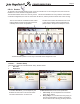
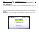
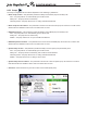
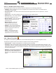
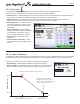
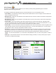
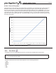
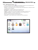
Table Of Contents
- Cover
- TABLE OF CONTENTS
- General Information
- SECTION 2 Venting and Combustion Air
- SECTION 3 Gas supply and Piping
- SECTION 4 Water Flow and Headloss Data
- SECTION 5 Boiler Piping
- SECTION 6 Condensate Drain Trap
- SECTION 7 Electrical Connections
- 7.A Installation Warnings
- 7.B Main Power Connections
- 7.C Main Power Data
- 7.D Control Panel Layout
- 7.E Field Connections
- 7.E.1 Power
- 7.E.2 Dry Contacts
- 7.E.3 Temperature Sensors
- 7.E.4 Safety Chain
- 7.E.5 Isolation Valve
- 7.E.6 Heat Demands
- 7.E.7 Analog In and Analog Out
- 7.E.8 Dry Contacts. Run & Alarm
- 7.E.9 RS 485 for Cascade (Lead Lag)
- 7.E.10 RS485 BMS
- 7.F Modbus to BACnet Memory Map (4 pages)
- 7.G WiringDiagram
- 7.H High Voltage Wiring Diagrams (5 pages)
- 7.I Ladder Diagrams (8 pages)
- SECTION 8 Control Operation
- 8.A The Home Screen
- 8.B Login to Lock / Unlock the Display Screen
- 8.C Quick Start
- 8.D Configuration
- 8.E Service Screens
- 8.E.1 Burner
- 8.E.2 Digital I/O ( Input / Output )
- 8.E.3 Analog I/O
- 8.E.4 Screen Settings Timeout
- 8.E.5 History
- 8.E.6 Restart Touchscreen & Recalibrate
- 8.E.7 Factory Reset
- 8.E.8 HMI Model OEM only
- 8.E.9 BIC Model OEM only
- 8.E.10 Both Model. OEM only.
- 8.E.11 About (the Firmware)
- 8.E.12 O2 (Trim Set Point)
- 8.E.13 LMV
- 8.F Messages and USB
- 8.G Active Demands
- SECTION 9 Parameter Tables (3 pages)
- SECTION 10 Initial startupInstructions
- SECTION 11 Maintenance
- SECTION 12 Troubleshooting
- SECTION 13 Replacement Parts
- 13.A Frame and Jacket Assembly, Part Numbers
- 13.B Control Panel Assembly, Part Numbers
- 13.C Blower and Burner Assembly,Part Numbers. ALL Sizes
- 13.D AC Distribution Box Assemblies and Part Numbers
- 13.E Burner Door Part Numbers
- 13.F Waterway Inlet Assembly, Part Numbers
- 13.G Waterway Outlet Assembly, Part Numbers
- 13.H Gas Train Part Numbers
- 13.I Exhaust Manifold Part Numbers

Page 84
CONFIGURATION
8.D.5.a Variable Speed Pump Control
The Variable Speed Pump Control Screen allows the adjustment of the following parameters:
• On Delay – Upon a call for heat, once the unit ignites, this is the amount of time the unit will wait prior to
modulating the pump speed.
• Proportional Gain – This value is the corrective action that is proportional to the error (Set Point – Control
Temperature).
• Integral Time – This value is applied to the sum of the error over a period of time.
• Derivative Time – This value is applied
to the rate of change of the error.
• Minimum Speed – This is the minimum
speed to which the Vari-Prime will
control the pump.
• Maximum Speed – The is the
maximum speed to which the
Vari-Prime will control the pump.
• O Delay – Once the heat demand is
satised, Vari-Prime will control to the
maximum pump speed until the O
Delay time expires.
• Delta T – Vari-Prime will control
the pump to maintain this delta T
(temperature rise) across the unit.
NOTE: VARI-PRIME
®
applies only to Boilers.
8.D.6 Manual Firing Rate
To navigate to the Manual Firing Rate Screen, touch the Manual Firing Rate Icon on the Conguration Screen.
The Manual Firing Rate Control Screen allows the adjustment of the following parameters:
• Enable/Disable – Enables and disables the manual ring rate functionality.
• Fan Speed – With the manual ring rate functionality enabled, an operator can manually set the ring rate. This
functionality is used for combustion adjustment purposes. With the manual ring rate functionality enabled, and the
desired fan speed set, apply a call for heat at CH1/DHW1 and the boiler will step through the ignition process and
run at the set fan speed.
• Time Out – is the amount of time that the
operator has to adjust the Manual Firing
Rate before the control will go back to
automatic. It’s a walkaway timer and safety
feature.