
Installation / Operation Instruction Manual
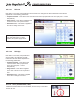
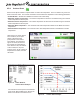
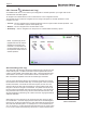
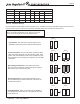
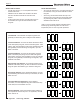
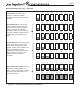
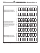
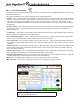

Table Of Contents
- Cover
- TABLE OF CONTENTS
- General Information
- SECTION 2 Venting and Combustion Air
- SECTION 3 Gas supply and Piping
- SECTION 4 Water Flow and Headloss Data
- SECTION 5 Boiler Piping
- SECTION 6 Condensate Drain Trap
- SECTION 7 Electrical Connections
- 7.A Installation Warnings
- 7.B Main Power Connections
- 7.C Main Power Data
- 7.D Control Panel Layout
- 7.E Field Connections
- 7.E.1 Power
- 7.E.2 Dry Contacts
- 7.E.3 Temperature Sensors
- 7.E.4 Safety Chain
- 7.E.5 Isolation Valve
- 7.E.6 Heat Demands
- 7.E.7 Analog In and Analog Out
- 7.E.8 Dry Contacts. Run & Alarm
- 7.E.9 RS 485 for Cascade (Lead Lag)
- 7.E.10 RS485 BMS
- 7.F Modbus to BACnet Memory Map (4 pages)
- 7.G WiringDiagram
- 7.H High Voltage Wiring Diagrams (5 pages)
- 7.I Ladder Diagrams (8 pages)
- SECTION 8 Control Operation
- 8.A The Home Screen
- 8.B Login to Lock / Unlock the Display Screen
- 8.C Quick Start
- 8.D Configuration
- 8.E Service Screens
- 8.E.1 Burner
- 8.E.2 Digital I/O ( Input / Output )
- 8.E.3 Analog I/O
- 8.E.4 Screen Settings Timeout
- 8.E.5 History
- 8.E.6 Restart Touchscreen & Recalibrate
- 8.E.7 Factory Reset
- 8.E.8 HMI Model OEM only
- 8.E.9 BIC Model OEM only
- 8.E.10 Both Model. OEM only.
- 8.E.11 About (the Firmware)
- 8.E.12 O2 (Trim Set Point)
- 8.E.13 LMV
- 8.F Messages and USB
- 8.G Active Demands
- SECTION 9 Parameter Tables (3 pages)
- SECTION 10 Initial startupInstructions
- SECTION 11 Maintenance
- SECTION 12 Troubleshooting
- SECTION 13 Replacement Parts
- 13.A Frame and Jacket Assembly, Part Numbers
- 13.B Control Panel Assembly, Part Numbers
- 13.C Blower and Burner Assembly,Part Numbers. ALL Sizes
- 13.D AC Distribution Box Assemblies and Part Numbers
- 13.E Burner Door Part Numbers
- 13.F Waterway Inlet Assembly, Part Numbers
- 13.G Waterway Outlet Assembly, Part Numbers
- 13.H Gas Train Part Numbers
- 13.I Exhaust Manifold Part Numbers

Page 75
minimum (instead of the allowable minimum ring rate of 5%). In addition, if the Drop Load Value is higher than the minimum
ring rate of the unit, the unit will turn o at the Drop Load Value and not the minimum ring rate of the unit.
Log In Settings
Parameter User Installer OEM Min Max Default Unit
Base Load X X 40 100 65 %
Drop Load X X 20 100 20 %
Min On Time X X 30 600 60 Seconds
Min O Time X X 30 600 30 Seconds
Table 19. Parameter Settings
1 2
30%
1 2 1 2
65%
30% 30%
1 2 1 2
100% 100%
65% 65%
1 2 1 2
20% 20% 20%
1 2 1 2
20%
Lead/Lag - 2 Boilers
Decreasing demand: As the demand decreases, once the requested
firing rate reaches the Drop Load Value , the second boiler turns off.
Boilers
Boilers
Demand Satisfied: When the heat demand is satisfied or the
temperature is at the set point + off hysteresis, the final boiler will turn
off.
Boilers
Boilers
Approaching max demand: Once both boilers reach 65%, both units
are allowed to increase firing rate (same at both boilers) up to
maximum firing rate.
Boilers
Boilers
Boilers
Boilers
Boilers
Increased demand: Once the first boiler reaches the Base Load Value
(65%) firing rate, the second boiler ignites. After ignition, both units
modulate to half of the cascade firing rate, then gradually increase the
firing rate together, up to the Base Load Value .
Low demand: The first boiler in sequence ignites and gradually
increases firing rate to satify the heat demand.
Low demand: The rst boiler in sequence ignites and
gradually increases ring rate to satify the heat demand.
Increased demand: Once the rst boiler reaches the Base
Load Value (65%) ring rate, the second boiler ignites. After
ignition, both units modulate to half of the cascade ring rate,
then gradually increase the ring rate together, up to the Base
Load Value.
Approaching max demand: Once both boilers reach
65%, both units are allowed to increase ring rate (same at
both boilers) up to maximum ring rate.
Decreasing demand: As the demand decreases, once
the requested ring rate reaches the Drop Load Value, the
second boiler turns o.
Demand Satised: When the heat demand is satised or
the temperature is at the set point + o hysteresis, the nal
boiler will turn o.
Figure 35. Lead / Lag, 2 Boilers
CONFIGURATION
NOTE: The single exception to a unit turning o at the Drop Load
Value in a cascade conguration is when there is only one unit
running, where the single unit acts as a standalone boiler.