
Installation / Operation Instruction Manual
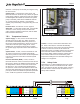
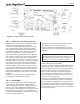
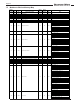
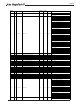
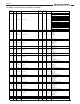
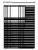
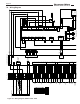
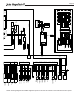
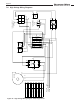
Table Of Contents
- Cover
- TABLE OF CONTENTS
- General Information
- SECTION 2 Venting and Combustion Air
- SECTION 3 Gas supply and Piping
- SECTION 4 Water Flow and Headloss Data
- SECTION 5 Boiler Piping
- SECTION 6 Condensate Drain Trap
- SECTION 7 Electrical Connections
- 7.A Installation Warnings
- 7.B Main Power Connections
- 7.C Main Power Data
- 7.D Control Panel Layout
- 7.E Field Connections
- 7.E.1 Power
- 7.E.2 Dry Contacts
- 7.E.3 Temperature Sensors
- 7.E.4 Safety Chain
- 7.E.5 Isolation Valve
- 7.E.6 Heat Demands
- 7.E.7 Analog In and Analog Out
- 7.E.8 Dry Contacts. Run & Alarm
- 7.E.9 RS 485 for Cascade (Lead Lag)
- 7.E.10 RS485 BMS
- 7.F Modbus to BACnet Memory Map (4 pages)
- 7.G WiringDiagram
- 7.H High Voltage Wiring Diagrams (5 pages)
- 7.I Ladder Diagrams (8 pages)
- SECTION 8 Control Operation
- 8.A The Home Screen
- 8.B Login to Lock / Unlock the Display Screen
- 8.C Quick Start
- 8.D Configuration
- 8.E Service Screens
- 8.E.1 Burner
- 8.E.2 Digital I/O ( Input / Output )
- 8.E.3 Analog I/O
- 8.E.4 Screen Settings Timeout
- 8.E.5 History
- 8.E.6 Restart Touchscreen & Recalibrate
- 8.E.7 Factory Reset
- 8.E.8 HMI Model OEM only
- 8.E.9 BIC Model OEM only
- 8.E.10 Both Model. OEM only.
- 8.E.11 About (the Firmware)
- 8.E.12 O2 (Trim Set Point)
- 8.E.13 LMV
- 8.F Messages and USB
- 8.G Active Demands
- SECTION 9 Parameter Tables (3 pages)
- SECTION 10 Initial startupInstructions
- SECTION 11 Maintenance
- SECTION 12 Troubleshooting
- SECTION 13 Replacement Parts
- 13.A Frame and Jacket Assembly, Part Numbers
- 13.B Control Panel Assembly, Part Numbers
- 13.C Blower and Burner Assembly,Part Numbers. ALL Sizes
- 13.D AC Distribution Box Assemblies and Part Numbers
- 13.E Burner Door Part Numbers
- 13.F Waterway Inlet Assembly, Part Numbers
- 13.G Waterway Outlet Assembly, Part Numbers
- 13.H Gas Train Part Numbers
- 13.I Exhaust Manifold Part Numbers

Page 50
7.H High Voltage Wiring Diagrams
Figure 24. High Voltage Wiring Diagram 120V, Single Phase
HH
N N
G
C
B
A
D
G
20AMP BREAKER
LINE
LOAD
1 2 3 4 5 6
TB2
5
4
6
12
3
120V
24V
Y
W
BK
BL
4 AMP
3
AMP
W
BK/O
T1
T2
A1 A2
CONTACTOR
L1 L2
BK
W
W
BK
W
G
BK
CONVENIENCE
RECEPTACLE
GFCI
2 AMP
N
G
H
10
AMP
2
AMP
BL
BL
BK
BK/O
W
G
Y
BL
TO CONNECTOR "E"
ON DIAGRAM
E23974
BK
BK
BK
BKBK
120 VAC
NEUTRAL
GRND
BK
W
G
BLOWER
G
L1
N
H2405100-
WIRING DIAGRAM
HIGH VOLTAGE, CFT
120V, 1Ø
WIRE COLOR LEGEND
BLACK
BK
BROWN
BR
RED
R
BLACK/ORANGE
BK/O
YELLOW
Y
GREEN
G
BLUE
BL
VIOLET
V
GRAY
GY
WHITE
W