
Installation / Operation Instruction Manual
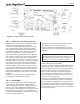
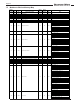
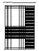
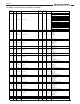
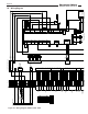
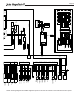
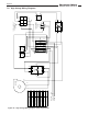
Table Of Contents
- Cover
- TABLE OF CONTENTS
- General Information
- SECTION 2 Venting and Combustion Air
- SECTION 3 Gas supply and Piping
- SECTION 4 Water Flow and Headloss Data
- SECTION 5 Boiler Piping
- SECTION 6 Condensate Drain Trap
- SECTION 7 Electrical Connections
- 7.A Installation Warnings
- 7.B Main Power Connections
- 7.C Main Power Data
- 7.D Control Panel Layout
- 7.E Field Connections
- 7.E.1 Power
- 7.E.2 Dry Contacts
- 7.E.3 Temperature Sensors
- 7.E.4 Safety Chain
- 7.E.5 Isolation Valve
- 7.E.6 Heat Demands
- 7.E.7 Analog In and Analog Out
- 7.E.8 Dry Contacts. Run & Alarm
- 7.E.9 RS 485 for Cascade (Lead Lag)
- 7.E.10 RS485 BMS
- 7.F Modbus to BACnet Memory Map (4 pages)
- 7.G WiringDiagram
- 7.H High Voltage Wiring Diagrams (5 pages)
- 7.I Ladder Diagrams (8 pages)
- SECTION 8 Control Operation
- 8.A The Home Screen
- 8.B Login to Lock / Unlock the Display Screen
- 8.C Quick Start
- 8.D Configuration
- 8.E Service Screens
- 8.E.1 Burner
- 8.E.2 Digital I/O ( Input / Output )
- 8.E.3 Analog I/O
- 8.E.4 Screen Settings Timeout
- 8.E.5 History
- 8.E.6 Restart Touchscreen & Recalibrate
- 8.E.7 Factory Reset
- 8.E.8 HMI Model OEM only
- 8.E.9 BIC Model OEM only
- 8.E.10 Both Model. OEM only.
- 8.E.11 About (the Firmware)
- 8.E.12 O2 (Trim Set Point)
- 8.E.13 LMV
- 8.F Messages and USB
- 8.G Active Demands
- SECTION 9 Parameter Tables (3 pages)
- SECTION 10 Initial startupInstructions
- SECTION 11 Maintenance
- SECTION 12 Troubleshooting
- SECTION 13 Replacement Parts
- 13.A Frame and Jacket Assembly, Part Numbers
- 13.B Control Panel Assembly, Part Numbers
- 13.C Blower and Burner Assembly,Part Numbers. ALL Sizes
- 13.D AC Distribution Box Assemblies and Part Numbers
- 13.E Burner Door Part Numbers
- 13.F Waterway Inlet Assembly, Part Numbers
- 13.G Waterway Outlet Assembly, Part Numbers
- 13.H Gas Train Part Numbers
- 13.I Exhaust Manifold Part Numbers

Page 41
Lag
Lead
GND
GND
GND
GND
GND
GND
120 N
120 N
120 N
120 N
120 L
120 L
120 L
120 L
24 N
24 N
24 N
24 N
24 L
24 L
24 L
24 L
BOILER PUMP N
BOILER PUMP L
AUXILIARY N
AUXILIARY L
DHW PUMP
DHW PUMP
SYSTEM PUMP
SYSTEM PUMP
ISOLATION VALVE
ISOLATION VALVE
ALARM BELL
ALARM BELL
SYSTEM SUPPLY
SYSTEM SUPPLY
SYSTEM RETURN
SYSTEM RETURN
DHW
DHW
OUTDOOR
OUTDOOR
FIELD INTERLOCK
FIELD INTERLOCK
PROOF OF
CLOSE
PROOF OF
OPEN
TT-1
TT-1
TT-2
TT-2
DHW
DHW
BMS 0-10VDC -
BMS 0-10VDC +
PUMP 0-10VDC -
PUMP 0-10VDC +
RUN - C
RUN - N.C.
RUN - N.O.
ALARM - C
ALARM - N.C.
ALARM - N.O.
CASCADE B
CASCADE A
CASCADE GND
BMS B
BMS A
BMS GND
1
2
3
4
5
6
7
8
9
10
11
12
13
14
15
16
17
18
19
20
21
22
23
24
25
26
27
28
29
30
31
32
33
34
35
36
37
38
39
40
41
42
43
44
45
46
47
48
49
50
51
52
53
54
55
56
57
58
59
60
61
62
63
64
65
66
67
68
69
70
RUN RELAY
CONTACTS
ALARM RELAY
CONTACTS
CASCADE
RS485
BMS RS485
ANALOG
OUTPUT
ANALOG
INPUT
SAFETY
CHAIN
ISOLATION
VALVE
HEAT DEMANDSTEMPERATURE SENSOR INPUTSDRY CONTACTS
POWER
OUTPUTS
120 VAC
H2406100A
24 VAC
GND
GND
GND
GND
GND
GND
120 N
120 N
120 N
120 N
120 L
120 L
120 L
120 L
24 N
24 N
24 N
24 N
24 L
24 L
24 L
24 L
BOILER PUMP N
BOILER PUMP L
AUXILIARY N
AUXILIARY L
DHW PUMP
DHW PUMP
SYSTEM PUMP
SYSTEM PUMP
ISOLATION VALVE
ISOLATION VALVE
ALARM BELL
ALARM BELL
SYSTEM SUPPLY
SYSTEM SUPPLY
SYSTEM RETURN
SYSTEM RETURN
DHW
DHW
OUTDOOR
OUTDOOR
FIELD INTERLOCK
FIELD INTERLOCK
PROOF OF
CLOSE
PROOF OF
OPEN
TT-1
TT-1
TT-2
TT-2
DHW
DHW
BMS 0-10VDC -
BMS 0-10VDC +
PUMP 0-10VDC -
PUMP 0-10VDC +
RUN - C
RUN - N.C.
RUN - N.O.
ALARM - C
ALARM - N.C.
ALARM - N.O.
CASCADE B
CASCADE A
CASCADE GND
BMS B
BMS A
BMS GND
1
2
3
4
5
6
7
8
9
10
11
12
13
14
15
16
17
18
19
20
21
22
23
24
25
26
27
28
29
30
31
32
33
34
35
36
37
38
39
40
41
42
43
44
45
46
47
48
49
50
51
52
53
54
55
56
57
58
59
60
61
62
63
64
65
66
67
68
69
70
RUN RELAY
CONTACTS
ALARM RELAY
CONTACTS
CASCADE
RS485
BMS RS485
ANALOG
OUTPUT
ANALOG
INPUT
SAFETY
CHAIN
ISOLATION
VALVE
HEAT DEMANDS
TEMPERATURE SENSOR INPUTSDRY CONTACTS
POWER
OUTPUTS
120 VAC
H2406100A
24 VAC
maximum. DHW pump functionality is congured using
the touch screen.
System Pump - If connecting a system pump, use
terminals 29 and 30. As this is a dry contact, the system
pump supply voltage or system pump relay coil voltage
would be applied at terminal 29, and when the system
pump is activated, power will be available at terminal
30. Contact ratings are 250VAC, 1.5A maximum.
System pump functionality is congured using the touch
screen.
Isolation Valve – See Section 7.E.5 on page 42
Alarm Bell – If connecting an alarm bell, use terminals
33 and 34. As this is a dry contact, the alarm bell
supply voltage is applied at terminal 33, with the alarm
bell connected to terminal 34.
7.E.3 Temperature Sensors
System Supply - If used, connect to terminals 35 and
36 (See Figure 20 on page 40). When connected,
the controller automatically detects the presence of
this sensor and the temperature is shown on the home
screen above the red system supply arrow. When
installed, the unit controls the ring rate to maintain
the system supply temperature to the heat demand set
point.
System Return - If used, connect to terminals 37 and
38. When connected, the controller automatically
detects the presence of this sensor and the temperature
is shown on the home screen above the blue system
output arrow.
Domestic Hot Water (DHW) - If used, connect to
terminals 39 and 40. When connected, the unit will use
this sensor to perform the DHW thermostat function and
the temperature is shown on the home screen below
the faucet icon. The controller automatically detects
the presence of this sensor and initiates a call for heat
when the DHW temperature drops below the DHW set
point by the value of the DHW On Hysteresis (DHW Set
Point – DHW On Hysteresis = DHW heat demand).
Outdoor - If used, is connected to terminals 41 and
42. When connected, the controller automatically
detects the presence of this sensor and the temperature
is shown on the home screen as the Outdoor air
Temperature (OAT). If installed, options such as outdoor
reset and warm weather shutdown can be enabled
through the display. Always install the Outdoor Sensor
at an outdoor location that is not aected by false
temperature readings such as elevated readings from
sunlight or hot equipment.
7.E.4 Safety Chain
Field Interlock - If a eld installed interlock (dry contact
only) is used, connect to terminals 43 and 44. When
open, the interlock will open the safety chain, removing
the heat demand. When closed, this interlock in the
safety chain is satised.
Figure 21. Hinged Control Panel
Hinged control panel
swings open for easy
servicing and setup