
Installation / Operation Instruction Manual
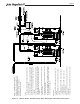
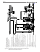
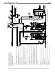
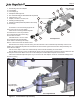
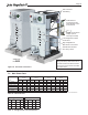
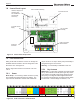
Table Of Contents
- Cover
- TABLE OF CONTENTS
- General Information
- SECTION 2 Venting and Combustion Air
- SECTION 3 Gas supply and Piping
- SECTION 4 Water Flow and Headloss Data
- SECTION 5 Boiler Piping
- SECTION 6 Condensate Drain Trap
- SECTION 7 Electrical Connections
- 7.A Installation Warnings
- 7.B Main Power Connections
- 7.C Main Power Data
- 7.D Control Panel Layout
- 7.E Field Connections
- 7.E.1 Power
- 7.E.2 Dry Contacts
- 7.E.3 Temperature Sensors
- 7.E.4 Safety Chain
- 7.E.5 Isolation Valve
- 7.E.6 Heat Demands
- 7.E.7 Analog In and Analog Out
- 7.E.8 Dry Contacts. Run & Alarm
- 7.E.9 RS 485 for Cascade (Lead Lag)
- 7.E.10 RS485 BMS
- 7.F Modbus to BACnet Memory Map (4 pages)
- 7.G WiringDiagram
- 7.H High Voltage Wiring Diagrams (5 pages)
- 7.I Ladder Diagrams (8 pages)
- SECTION 8 Control Operation
- 8.A The Home Screen
- 8.B Login to Lock / Unlock the Display Screen
- 8.C Quick Start
- 8.D Configuration
- 8.E Service Screens
- 8.E.1 Burner
- 8.E.2 Digital I/O ( Input / Output )
- 8.E.3 Analog I/O
- 8.E.4 Screen Settings Timeout
- 8.E.5 History
- 8.E.6 Restart Touchscreen & Recalibrate
- 8.E.7 Factory Reset
- 8.E.8 HMI Model OEM only
- 8.E.9 BIC Model OEM only
- 8.E.10 Both Model. OEM only.
- 8.E.11 About (the Firmware)
- 8.E.12 O2 (Trim Set Point)
- 8.E.13 LMV
- 8.F Messages and USB
- 8.G Active Demands
- SECTION 9 Parameter Tables (3 pages)
- SECTION 10 Initial startupInstructions
- SECTION 11 Maintenance
- SECTION 12 Troubleshooting
- SECTION 13 Replacement Parts
- 13.A Frame and Jacket Assembly, Part Numbers
- 13.B Control Panel Assembly, Part Numbers
- 13.C Blower and Burner Assembly,Part Numbers. ALL Sizes
- 13.D AC Distribution Box Assemblies and Part Numbers
- 13.E Burner Door Part Numbers
- 13.F Waterway Inlet Assembly, Part Numbers
- 13.G Waterway Outlet Assembly, Part Numbers
- 13.H Gas Train Part Numbers
- 13.I Exhaust Manifold Part Numbers

Page 38
SECTION 7 Electrical Connections
7.A Installation Warnings
CAUTION
The supply voltage to this unit must not be
disconnected, except for service or isolation, or
unless otherwise instructed by procedures outlined
in this manual. To signal a call for heat, use the heat
demand inputs, as shown in the wiring diagram.
DO NOT MAKE AND BREAK THE LINE VOLTAGE
TO THE UNIT TO SIGNAL A CALL FOR HEAT. A
call for heat/end call for heat MUST be connected to
the heat demand terminals. Some components are
designed to have constant voltage during normal
operation. If the units supply voltage is toggled as
a call for heat signal, premature failure of these
components may result.
The unit does not recognize 4mA as a signal to shut
o. If the call for heat is not connected between the
eld interlock terminals, the unit will remain in low
re when it sees 4mA as a modulating signal.
WARNING
The unit must be electrically grounded in accordance
with the requirements of the authority having
jurisdiction or, in the absence of such requirements,
with the latest edition of the National Electrical Code,
ANSI/NFPA 70, in the U.S. and with the latest edition
of CSA C22.1 Canadian Electrical Code, Part 1, in
Canada. Do not rely on the gas or water piping to
ground the metal parts of the unit. Plastic pipe or
dielectric unions may isolate the unit electrically.
Service and maintenance personnel, who work on
or around the unit, may be standing on wet oors
and could be electrocuted by an ungrounded unit.
Electrocution can result in severe injury or death.
Single pole switches, including those of safety
controls and protective devices, must not be wired in
a grounded line.
All electrical connections are made on the terminal
blocks that are located inside the control panel.
All internal electrical components have been prewired.
No attempt should be made to connect electrical wires
to any other location except the terminal blocks.
CAUTION
Label all wires prior to disconnection when servicing
controls. Wiring errors can cause improper and
dangerous operation. Verify proper operation after
operation servicing.
ATTENTION
Au moment de l’entretien des commandes,
étiquetez tous les ls avant de les débrancher.
Les erreurs de câblage peuvent nuire au bon
fonctionnement et être dangereuses. S’assurer
que l’appareil fonctionne adéquatement une fois
l’entretien terminé.
This unit is provided with an electrical junction boxes
on the rear panel for main power connections. See
Figure 18. All power wires are factory installed
between this junction box and the main high voltage
box at the front of the unit. The unit is available with
multiple voltage packages to adapt to customer needs
ranging from 120-600 volts with single or three phase
versions. Refer to the rating plate and “” on page 39
for appropriate voltage and current ratings.
As a common industry practice, the manufacturer has
color coded the single and three phase wires as shown
in Table 17.
On single phase models, the incoming voltage will be
protected by the appropriate circuit breaker, sized and
installed by a qualied electrician/authorized personnel.
The 120-volt and 24-volt systems will be protected with
resettable fuses mounted in the top of the high voltage
box. The 24-volt transformer is also redundantly
protected by its integrated 4 amp resettable fuse.
On three phase models, a step down transformer
(which is protected using an appropriate din rail
mounted circuit breaker) generates 120-volt single
phase to power the 24-volt transformer. The 120-
volt and 24-volt outputs of either transformer are
protected with resettable fuses mounted in the top
of the high voltage box. The 24-volt transformer is
also redundantly protected by its integrated 4 amp
resettable fuse.
7.B Main Power Connections