
Installation / Operation Instruction Manual
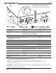
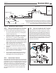
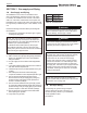
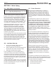
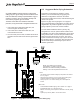
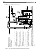
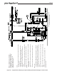
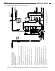
Table Of Contents
- Cover
- TABLE OF CONTENTS
- General Information
- SECTION 2 Venting and Combustion Air
- SECTION 3 Gas supply and Piping
- SECTION 4 Water Flow and Headloss Data
- SECTION 5 Boiler Piping
- SECTION 6 Condensate Drain Trap
- SECTION 7 Electrical Connections
- 7.A Installation Warnings
- 7.B Main Power Connections
- 7.C Main Power Data
- 7.D Control Panel Layout
- 7.E Field Connections
- 7.E.1 Power
- 7.E.2 Dry Contacts
- 7.E.3 Temperature Sensors
- 7.E.4 Safety Chain
- 7.E.5 Isolation Valve
- 7.E.6 Heat Demands
- 7.E.7 Analog In and Analog Out
- 7.E.8 Dry Contacts. Run & Alarm
- 7.E.9 RS 485 for Cascade (Lead Lag)
- 7.E.10 RS485 BMS
- 7.F Modbus to BACnet Memory Map (4 pages)
- 7.G WiringDiagram
- 7.H High Voltage Wiring Diagrams (5 pages)
- 7.I Ladder Diagrams (8 pages)
- SECTION 8 Control Operation
- 8.A The Home Screen
- 8.B Login to Lock / Unlock the Display Screen
- 8.C Quick Start
- 8.D Configuration
- 8.E Service Screens
- 8.E.1 Burner
- 8.E.2 Digital I/O ( Input / Output )
- 8.E.3 Analog I/O
- 8.E.4 Screen Settings Timeout
- 8.E.5 History
- 8.E.6 Restart Touchscreen & Recalibrate
- 8.E.7 Factory Reset
- 8.E.8 HMI Model OEM only
- 8.E.9 BIC Model OEM only
- 8.E.10 Both Model. OEM only.
- 8.E.11 About (the Firmware)
- 8.E.12 O2 (Trim Set Point)
- 8.E.13 LMV
- 8.F Messages and USB
- 8.G Active Demands
- SECTION 9 Parameter Tables (3 pages)
- SECTION 10 Initial startupInstructions
- SECTION 11 Maintenance
- SECTION 12 Troubleshooting
- SECTION 13 Replacement Parts
- 13.A Frame and Jacket Assembly, Part Numbers
- 13.B Control Panel Assembly, Part Numbers
- 13.C Blower and Burner Assembly,Part Numbers. ALL Sizes
- 13.D AC Distribution Box Assemblies and Part Numbers
- 13.E Burner Door Part Numbers
- 13.F Waterway Inlet Assembly, Part Numbers
- 13.G Waterway Outlet Assembly, Part Numbers
- 13.H Gas Train Part Numbers
- 13.I Exhaust Manifold Part Numbers

Page 27
Air Vent
On innitial installations, drain and ush the system before
adding propylene glycol. Sludge and other sediments in the
boiler can inhibit ow, resulting in rapid breakdown of glycol.
Check the propylene glycol concentration annually. Add
more water or propylene glycol as needed.
The boiler control oers some assistance with freeze
protection, as long as the boiler is energized and able to re.
1. If the outlet sensor detects less than 45°F, the
control energizes the boiler pump.
2. If the outlet sensor detects less than 35°F, the
control will re at low rate.
3. Once in freeze protect mode, the boiler will remain in
that state until the outlet sensor detects greater than
50°F.
5.D Suggested Boiler Piping Schematics
This boiler is a high eciency appliance. Boiler
eciency can be maximized by using piping and
distribution congurations that return the lowest
temperature possible to the boiler, while still meeting the
needs of the system.
Figure 8 on page 27 through Figure 15 on page 34
show suggested piping congurations for boilers. These
diagrams are only meant as guides. All components or
piping required by local code must be installed.
For multi-boiler installations where a primary only
conguration is used, an optional water isolation valve
is available. This valve is eld installed but comes with a
wiring harness which connects with pre-installed boiler
wiring via a quick disconnect connector. The control
system contains the necessary logic to open and close
the insolation valves in conjunction with the boiler heat
demand while always maintaining an open valve to
maintain system ow.
NOTE: This drawing is a schematic
representation of a piping style and is not
intended to be used as a working installation
drawing. Local code requirements must be met.
Control:
• Use outdoor reset to maintain building loop temperature. See Section
8.C.3 on page 67.
• Set System pump to AUTO, pump runs during space heating when
outdoor temperature is below warm weather shutdown.
• Place jumper on T-T for constant heating call; or interrupted if so
desired.
BMS control:
• For Modbus/BACnet BMS mapping, refer to Section 7.F on page 44.
• Enable/disable boiler via T-T terminals (49, 50).
• BMS can control ring rate or setpoint via terminals 55 and 56. (analog
input).
• System pump control by BMS or Touchscreen Control.
Figure 8. Single Boiler, Variable Primary, Space Heating only