
Installation / Operation Instruction Manual
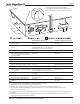
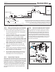
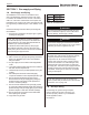
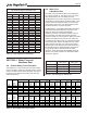
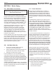
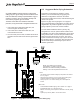
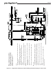
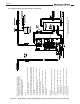
Table Of Contents
- Cover
- TABLE OF CONTENTS
- General Information
- SECTION 2 Venting and Combustion Air
- SECTION 3 Gas supply and Piping
- SECTION 4 Water Flow and Headloss Data
- SECTION 5 Boiler Piping
- SECTION 6 Condensate Drain Trap
- SECTION 7 Electrical Connections
- 7.A Installation Warnings
- 7.B Main Power Connections
- 7.C Main Power Data
- 7.D Control Panel Layout
- 7.E Field Connections
- 7.E.1 Power
- 7.E.2 Dry Contacts
- 7.E.3 Temperature Sensors
- 7.E.4 Safety Chain
- 7.E.5 Isolation Valve
- 7.E.6 Heat Demands
- 7.E.7 Analog In and Analog Out
- 7.E.8 Dry Contacts. Run & Alarm
- 7.E.9 RS 485 for Cascade (Lead Lag)
- 7.E.10 RS485 BMS
- 7.F Modbus to BACnet Memory Map (4 pages)
- 7.G WiringDiagram
- 7.H High Voltage Wiring Diagrams (5 pages)
- 7.I Ladder Diagrams (8 pages)
- SECTION 8 Control Operation
- 8.A The Home Screen
- 8.B Login to Lock / Unlock the Display Screen
- 8.C Quick Start
- 8.D Configuration
- 8.E Service Screens
- 8.E.1 Burner
- 8.E.2 Digital I/O ( Input / Output )
- 8.E.3 Analog I/O
- 8.E.4 Screen Settings Timeout
- 8.E.5 History
- 8.E.6 Restart Touchscreen & Recalibrate
- 8.E.7 Factory Reset
- 8.E.8 HMI Model OEM only
- 8.E.9 BIC Model OEM only
- 8.E.10 Both Model. OEM only.
- 8.E.11 About (the Firmware)
- 8.E.12 O2 (Trim Set Point)
- 8.E.13 LMV
- 8.F Messages and USB
- 8.G Active Demands
- SECTION 9 Parameter Tables (3 pages)
- SECTION 10 Initial startupInstructions
- SECTION 11 Maintenance
- SECTION 12 Troubleshooting
- SECTION 13 Replacement Parts
- 13.A Frame and Jacket Assembly, Part Numbers
- 13.B Control Panel Assembly, Part Numbers
- 13.C Blower and Burner Assembly,Part Numbers. ALL Sizes
- 13.D AC Distribution Box Assemblies and Part Numbers
- 13.E Burner Door Part Numbers
- 13.F Waterway Inlet Assembly, Part Numbers
- 13.G Waterway Outlet Assembly, Part Numbers
- 13.H Gas Train Part Numbers
- 13.I Exhaust Manifold Part Numbers

Page 25
SCH 40 METAL PIPE CAPACITY FOR
0.60 SPECIFIC GRAVITY NATURAL GAS
NOMINAL PIPE SIZE
@
0.50” W.C. PRESSURE DROP
Nominal: 2” 2½” 3” 4” 5” Nominal: 1½ 2 2½ 3 4
Actual ID: 2.067” 2.469” 3.068” 4.026” 5.047” Actual ID: 1.61 2.067 2.469 3.068 4.026
Length (ft) Length (ft)
10 4,020 6,400 11,300 23,100 41,800 10 3,520 6,790 10,800 19,100 39,000
20 2,760 4,400 7,780 15,900 28,700 20 2,420 4,660 7,430 13,100 26,800
30 2,220 3,530 6,250 12,700 23,000 30 1,940 3,750 5,970 10,600 21,500
40 1,900 3,020 5,350 10,900 19,700 40 1,660 3,210 5,110 9,030 18,400
50 1,680 2,680 4,740 9,660 17,500 50 1,480 2,840 4,530 8,000 16,300
60 1,520 2,430 4,290 8,760 15,800 60 1,340 2,570 4,100 7,250 14,800
70 1,400 2,230 3,950 8,050 14,600 80 1,230 2,370 3,770 6,670 13,600
80 1,300 2,080 3,670 7,490 13,600 10
0 1,140 2,200 3,510 6,210 124,700
90 1,220 1,950 3,450 7,030 12,700 125 1,070 2,070 3,290 5,820 11,900
100 1,160 1,840 3,260 6,640 12,000 150 1,010 1,950 3,110 5,500 11,200
125 1,020 1,630 2,890 5,890 10,600 175 899 1,730 2,760 4,880 9,950
150 928 1,480 2,610 5,330 9,650 200 814 1,570 2,500 4,420 9,010
175 854 1,360 2,410 4,910 8,880 250 749 1,440 2,300 4,060 8,290
200 794 1,270 2,240 4,560 8,260 300 697 1,340 2,140 3,780 7,710
150 704 1,120 1,980 4,050 7,320 350 618 1,190 1,900 3,350 6,840
300 638 1,020 1,800 3,670 6,630 400 560 1,080 1,720 3,040 6,190
350 587 935 1,650 3,370 6,100
NOTES:
400 546 870 1,540 3,140 5,680
1. Inlet pres
sur
e - 11.0 in w.c.
NOTES:
2. Pressure drop - 0.5 in w.c.
1. Inlet pressure - Less than 2 psi
3. Specific gravity - 1.50
2. Pressure drop - 0.5 in w.c.
4. Schedule 40 metallic pipe
3. Specific gravity - 0.60
5. Intended use - Pipe sizing between single
4. Schedule 40 metallic pipe
or second-stage (low pressure)
regulator and appliance.
Capacity in Cubic Feet of Gas per Hour
Pipe Size (in.)
Natural Gas
Undiluted Propane
Pipe Size (in.)
Capacity in Cubic Feet of Gas per Hour
Table 13. Pipe Capacity for Natural Gas
Table 15. Pipe Capacity for Natural Gas
Table 14. Boiler Water Flow and Headloss
4.B
The water flow and headloss data for the Magnatherm FT is shown in Table 14. This data is given for various water differential temperatures at full boiler input
rate.
The Magantherm FT must be configured in a closed loop configuration and fill operations should be limited. If the system needs to be refilled frequently, check
for leaks in the primary water circuit. The boiler water hardness should be kept below 10 grains per gallon.
The Magnatherm FT is equipped with a water flow switch in the boiler exit nozzle which will prevent operation of the boiler if the water flow is below
approximately 10 gallons per minute. This switch is part of the main safety circuit and prevents boiler operation when there is little or no flow but allows for
adjusting boiler pump speed to maintain reasonable differential water temperatures at low fire. The control system is also equipped with a water Delta T
feature which determines the allowable maximum differential water temperatures for a given input rate at which the boiler can safely operate at. These
parameters are adjustable within pre-set limits. For further information on this feature please see Section 8.D.8
Size
Output
Max
Btu/hr
20
o
F
30
o
F
40
o
F
50
o
F
60
o
F
70
o
F
Flow
GPM
Head
Loss Feet
Flow
GPM
Head
Loss
Feet
Flow
GPM
Head
Loss
Feet
Flow
GPM
Head
Loss
Feet
Flow
GPM
Head
Loss
Feet
Flow
GPM
Head
Loss
Feet
1000
950000
95.0
1.9
63.3
1.1
47.5
0.72
38.0
0.53
31.7
0.41
27.1
0.33
1500
1425000
142.4
3.4
95.0
1.6
71.2
0.96
57.0
0.64
47.5
0.46
40.7
0.34
2000
1900000
189.9
4.5
126.6
2.1
95.0
1.2
76.0
0.82
63.3
0.58
54.3
0.44
3000
2850000
284.9
7.0
189.9
3.5
142.4
2.1
113.9
1.4
95.0
1.0
81.4
0.79
Size
Output
Max
Btu/hr
11
o
C
17
o
C
22
o
C
28
o
C
33
o
C
39
o
C
Flow
GPM
Head
Loss Feet
Flow
GPM
Head
Loss
Feet
Flow
GPM
Head
Loss
Feet
Flow
GPM
Head
Loss
Feet
Flow
GPM
Head
Loss
Feet
Flow
GPM
Head
Loss
Feet
1000
950000
359
0.59
240
0.33
180
0.22
144
0.16
120
0.12
103
0.10
1500
1425000
539
1.03
359
0.49
270
0.29
216
0.19
180
0.14
154
0.10
2000
1900000
719
1.38
479
0.65
359
0.38
288
0.25
240
0.18
205
0.13
3000
2850000
1078
2.15
719
1.06
539
0.64
431
0.43
359
0.32
308
0.24
SECTION 4 Water Flow and
Headloss Data
4.A General Water Flow Information
This appliance is a re-tube design that requires water
ow for operation. Boilers are generally used in closed
systems, so Manufacturer bases the water ow data on
temperature rise (dierence between boiler inlet and
outlet temperature.)
4.B Water Flow
& Headloss Data
The water ow and headloss data for the MagnaTech
FT is shown in Table 14 This data is given for various
water temperature rises at full boiler input rate.
The MagnaTech FT must be congured in a closed loop
conguration and ll operations should be limited. If the
system needs to be relled frequently, check for leaks
in the primary water circuit. The boiler water hardness
should be kept below 10 grains per gallon.
The MagnaTech FT is equipped with a water ow switch
in the boiler outlet which will prevent operation of the
boiler if the water ow is below approximately
20 gallons per minute. This water ow switch is part of
the main safety circuit and prevents boiler operation
when there is little or no ow at low re. Table 15 provides
maximum and minimum ow rates for each boiler size.
The minimum ow rate is at low re conditions with water
as the heating uid. Boilers with antifreeze may require
higher minimum ow rates. The control system is also
equipped with a water Delta T feature which determines
the allowable maximum dierential water temperatures
for a given input rate at which the boiler can safely
operate at. These parameters are adjustable within pre-
set limits. For further information on this feature please
see 8.D.8 on page 87
Size Maximum Flow
Rate (gpm)
Minimum Flow
Rate (gpm)
1000 250 20
1500 250 25
2000 250 25
3000 250 30