
Installation / Operation Instruction Manual
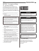
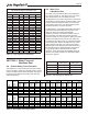
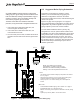
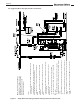
Table Of Contents
- Cover
- TABLE OF CONTENTS
- General Information
- SECTION 2 Venting and Combustion Air
- SECTION 3 Gas supply and Piping
- SECTION 4 Water Flow and Headloss Data
- SECTION 5 Boiler Piping
- SECTION 6 Condensate Drain Trap
- SECTION 7 Electrical Connections
- 7.A Installation Warnings
- 7.B Main Power Connections
- 7.C Main Power Data
- 7.D Control Panel Layout
- 7.E Field Connections
- 7.E.1 Power
- 7.E.2 Dry Contacts
- 7.E.3 Temperature Sensors
- 7.E.4 Safety Chain
- 7.E.5 Isolation Valve
- 7.E.6 Heat Demands
- 7.E.7 Analog In and Analog Out
- 7.E.8 Dry Contacts. Run & Alarm
- 7.E.9 RS 485 for Cascade (Lead Lag)
- 7.E.10 RS485 BMS
- 7.F Modbus to BACnet Memory Map (4 pages)
- 7.G WiringDiagram
- 7.H High Voltage Wiring Diagrams (5 pages)
- 7.I Ladder Diagrams (8 pages)
- SECTION 8 Control Operation
- 8.A The Home Screen
- 8.B Login to Lock / Unlock the Display Screen
- 8.C Quick Start
- 8.D Configuration
- 8.E Service Screens
- 8.E.1 Burner
- 8.E.2 Digital I/O ( Input / Output )
- 8.E.3 Analog I/O
- 8.E.4 Screen Settings Timeout
- 8.E.5 History
- 8.E.6 Restart Touchscreen & Recalibrate
- 8.E.7 Factory Reset
- 8.E.8 HMI Model OEM only
- 8.E.9 BIC Model OEM only
- 8.E.10 Both Model. OEM only.
- 8.E.11 About (the Firmware)
- 8.E.12 O2 (Trim Set Point)
- 8.E.13 LMV
- 8.F Messages and USB
- 8.G Active Demands
- SECTION 9 Parameter Tables (3 pages)
- SECTION 10 Initial startupInstructions
- SECTION 11 Maintenance
- SECTION 12 Troubleshooting
- SECTION 13 Replacement Parts
- 13.A Frame and Jacket Assembly, Part Numbers
- 13.B Control Panel Assembly, Part Numbers
- 13.C Blower and Burner Assembly,Part Numbers. ALL Sizes
- 13.D AC Distribution Box Assemblies and Part Numbers
- 13.E Burner Door Part Numbers
- 13.F Waterway Inlet Assembly, Part Numbers
- 13.G Waterway Outlet Assembly, Part Numbers
- 13.H Gas Train Part Numbers
- 13.I Exhaust Manifold Part Numbers

Page 24
NOTE: This unit and all other gas units sharing the
gas supply line must be ring at maximum capacity
to properly measure the inlet supply pressure.
The pressure can be measured at the supply
pressure port on the gas valve. Low gas pressure
could be an indication of an undersized gas meter,
undersized gas supply lines and/or an obstructed
gas supply line. The units may be equipped with low
and high pressure gas switches that are integrally
vent limited. These types of devices do not require
venting to atmosphere.
NOTE: After placing the boiler in operation, the
ignition system safety shuto device must be tested.
See Section 10.A on page 108
SECTION 3 Gas supply and Piping
3.A Gas Supply and Piping
All Installations must conform to the National Fuel
Gas Code ANSI Z223.1/NFPA54, and/or local codes.
In Canada, the installation must conform to the latest
edition of CSA B149.1 Natural Gas and Propane Gas
Installation Code, and/or local codes. Gas piping should
be supported by suitable hangers or oor stands, not the
unit.
Review the following instructions before proceeding with
the installation.
1. Verify that the unit is tted for the proper type of gas by
checking the rating plate.
NOTE: This unit is equipped to operate at elevations
up to 2000 feet (610m). However, the unit will function
properly without the use of high altitude modication at
elevations up to 10,000 feet (3050 m).
For elevations above 2000 ft (600 m), the input gas
rating shall be reduced at a rate of 4 percent for each
1000 ft (300 m) above sea level. This must be considered
before selecting the equipment size.
2. The gas pressure settings are shown in Table 12.
3. Table 13 oers some gas pipe sizing sizing information.
Refer to the applicable gas code for more detailed
sizing information.
4. Run gas supply line in accordance with all applicable
codes.
5. Locate and install manual shuto valves in accordance
with state and local requirements.
6. A sediment trap must be provided upstream of the gas
controls.
7. All threaded joints should be coated with piping
compound resistant to action of liquied petroleum gas.
8. The unit and its individual shuto valve must be
disconnected from the gas supply piping during any
pressure testing of that system at test pressures in
excess of 1/2 PSIG (3.45kpa).
9. The unit must be isolated from the gas supply system
by closing its individual manual shuto valve during any
pressure testing of the gas supply piping system at test
pressures equal to or less than 1/2 PSIG (3.45kpa).
10. The unit and its gas connection must be leak tested
before placing it in operation.
11. Purge all air from gas lines
Table 12. Gas Pressure
WARNING
Do not use open ame to check for leaks. An open
ame could lead to explosion, which could result in
property damage, serious injury or death.
WARNING
If an inline high gas pressure regulator is used, it
must be of the lockup type and located a minimum
of 10 feet from the unit. Failure to do so may result in
insucient gas volume supplied to the unit.
The following are gas line sizing examples
from the National Fuel Gas Code. Size your
gas lines properly, based on your installation
and all applicable codes.
See Table 13
3.B Gas Pipe Sizing
Natural Gas LP (propane)
Min 4.0 IN - W.C. 8.0 IN - W.C.
Max 10.5 IN - W.C. 13.0 IN - W.C.