
Installation / Operation Instruction Manual
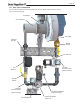
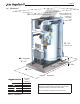
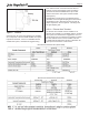
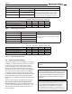
Table Of Contents
- Cover
- TABLE OF CONTENTS
- General Information
- SECTION 2 Venting and Combustion Air
- SECTION 3 Gas supply and Piping
- SECTION 4 Water Flow and Headloss Data
- SECTION 5 Boiler Piping
- SECTION 6 Condensate Drain Trap
- SECTION 7 Electrical Connections
- 7.A Installation Warnings
- 7.B Main Power Connections
- 7.C Main Power Data
- 7.D Control Panel Layout
- 7.E Field Connections
- 7.E.1 Power
- 7.E.2 Dry Contacts
- 7.E.3 Temperature Sensors
- 7.E.4 Safety Chain
- 7.E.5 Isolation Valve
- 7.E.6 Heat Demands
- 7.E.7 Analog In and Analog Out
- 7.E.8 Dry Contacts. Run & Alarm
- 7.E.9 RS 485 for Cascade (Lead Lag)
- 7.E.10 RS485 BMS
- 7.F Modbus to BACnet Memory Map (4 pages)
- 7.G WiringDiagram
- 7.H High Voltage Wiring Diagrams (5 pages)
- 7.I Ladder Diagrams (8 pages)
- SECTION 8 Control Operation
- 8.A The Home Screen
- 8.B Login to Lock / Unlock the Display Screen
- 8.C Quick Start
- 8.D Configuration
- 8.E Service Screens
- 8.E.1 Burner
- 8.E.2 Digital I/O ( Input / Output )
- 8.E.3 Analog I/O
- 8.E.4 Screen Settings Timeout
- 8.E.5 History
- 8.E.6 Restart Touchscreen & Recalibrate
- 8.E.7 Factory Reset
- 8.E.8 HMI Model OEM only
- 8.E.9 BIC Model OEM only
- 8.E.10 Both Model. OEM only.
- 8.E.11 About (the Firmware)
- 8.E.12 O2 (Trim Set Point)
- 8.E.13 LMV
- 8.F Messages and USB
- 8.G Active Demands
- SECTION 9 Parameter Tables (3 pages)
- SECTION 10 Initial startupInstructions
- SECTION 11 Maintenance
- SECTION 12 Troubleshooting
- SECTION 13 Replacement Parts
- 13.A Frame and Jacket Assembly, Part Numbers
- 13.B Control Panel Assembly, Part Numbers
- 13.C Blower and Burner Assembly,Part Numbers. ALL Sizes
- 13.D AC Distribution Box Assemblies and Part Numbers
- 13.E Burner Door Part Numbers
- 13.F Waterway Inlet Assembly, Part Numbers
- 13.G Waterway Outlet Assembly, Part Numbers
- 13.H Gas Train Part Numbers
- 13.I Exhaust Manifold Part Numbers

Page 20
2.C.5.b Ducted Combustion Air
The combustion air can be taken through the wall, or
through the roof. The manufacturer oers accessories
to use with ducted air systems, as shown in Table 9.
See Table 8 to select the appropriate diameter air pipe.
When taken from the roof, a eld-supplied rain cap or
an elbow arrangement must be used to prevent entry of
rain water. (See Figure 7).
Use ABS, PVC, CPVC, polypropylene, stainless steel,
or galvanized pipe for the combustion air intake (See
Table 8 for allowable materials). The intake must be
sized per Table 1 on page 8. Route the intake to
the boiler as directly as possible. Seal all joints. Provide
adequate hangers. The unit must not support the
weight of the combustion air intake pipe. The maximum
equivalent pipe length allowed is 100 feet (30 m).
Each elbow is considered to be 5 feet (1.5m).
When using polypropylene or stainless steel materials
in horizontal duct congurations, a single elbow must
be installed on the end of the air inlet to act as an
outdoor terminal. In vertical duct applications, two
elbows must be installed on the end of the inlet to act
as a vent terminal. When elbows are use as terminals,
appropriate screens must be installed to prevent
blockage.
The elbow(s) required for termination are not included in
the kits shown in Table 9.
The connection for the intake air pipe is on the back
panel.
In addition to air needed for combustion, air shall also
be supplied for ventilation, including air required for
comfort and proper working conditions for personnel.
Refer to the applicable codes.
2.D Locating the Vent and Combustion Air
Terminals
2.D.1 Side-wall Vent Terminal
The appropriate side-wall vent terminal must be used.
The terminal must be located in accordance with
ANSI Z223.1/NFPA 54 and applicable local codes. In
Canada, the installation must be in accordance with
CSA B149.1 or .2 and local applicable codes.
Consider the following when installing the terminal:
1. Figure 6 on page 22 shows the requirements for
mechanical vent terminal clearances for the U.S.
and Canada.
2. Vent terminals for condensing units or units with
condensing vents are not permitted to terminate
above a public walkway, or over an area where
condensate or vapor could create a nuisance or
hazard.
3. Locate the vent terminal so that vent gases cannot
be drawn into air conditioning system inlets.
4. Locate the vent terminal so that vent gases cannot
enter the building through doors, windows, gravity
inlets or other openings. Whenever possible, avoid
locations under windows or near doors.
5. Locate the vent terminal so that it cannot be
blocked by snow. The installer may determine that
a vent terminal must be higher than the minimum
shown in codes, depending upon local conditions.
6. Locate the terminal so the vent exhaust does not
settle on building surfaces or other nearby objects.
Vent exhaust bi-products may damage surfaces or
objects.
7. If the boiler or boiler uses ducted combustion
air from an intake terminal located on the same
wall, see See Figure 6 on page 22 for proper
spacing and orientation.