
Installation / Operation Instruction Manual

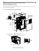
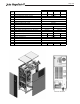
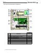
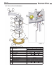
Table Of Contents
- Cover
- TABLE OF CONTENTS
- General Information
- SECTION 2 Venting and Combustion Air
- SECTION 3 Gas supply and Piping
- SECTION 4 Water Flow and Headloss Data
- SECTION 5 Boiler Piping
- SECTION 6 Condensate Drain Trap
- SECTION 7 Electrical Connections
- 7.A Installation Warnings
- 7.B Main Power Connections
- 7.C Main Power Data
- 7.D Control Panel Layout
- 7.E Field Connections
- 7.E.1 Power
- 7.E.2 Dry Contacts
- 7.E.3 Temperature Sensors
- 7.E.4 Safety Chain
- 7.E.5 Isolation Valve
- 7.E.6 Heat Demands
- 7.E.7 Analog In and Analog Out
- 7.E.8 Dry Contacts. Run & Alarm
- 7.E.9 RS 485 for Cascade (Lead Lag)
- 7.E.10 RS485 BMS
- 7.F Modbus to BACnet Memory Map (4 pages)
- 7.G WiringDiagram
- 7.H High Voltage Wiring Diagrams (5 pages)
- 7.I Ladder Diagrams (8 pages)
- SECTION 8 Control Operation
- 8.A The Home Screen
- 8.B Login to Lock / Unlock the Display Screen
- 8.C Quick Start
- 8.D Configuration
- 8.E Service Screens
- 8.E.1 Burner
- 8.E.2 Digital I/O ( Input / Output )
- 8.E.3 Analog I/O
- 8.E.4 Screen Settings Timeout
- 8.E.5 History
- 8.E.6 Restart Touchscreen & Recalibrate
- 8.E.7 Factory Reset
- 8.E.8 HMI Model OEM only
- 8.E.9 BIC Model OEM only
- 8.E.10 Both Model. OEM only.
- 8.E.11 About (the Firmware)
- 8.E.12 O2 (Trim Set Point)
- 8.E.13 LMV
- 8.F Messages and USB
- 8.G Active Demands
- SECTION 9 Parameter Tables (3 pages)
- SECTION 10 Initial startupInstructions
- SECTION 11 Maintenance
- SECTION 12 Troubleshooting
- SECTION 13 Replacement Parts
- 13.A Frame and Jacket Assembly, Part Numbers
- 13.B Control Panel Assembly, Part Numbers
- 13.C Blower and Burner Assembly,Part Numbers. ALL Sizes
- 13.D AC Distribution Box Assemblies and Part Numbers
- 13.E Burner Door Part Numbers
- 13.F Waterway Inlet Assembly, Part Numbers
- 13.G Waterway Outlet Assembly, Part Numbers
- 13.H Gas Train Part Numbers
- 13.I Exhaust Manifold Part Numbers

Page 125
View from the back
1000 1500 2000 3000
ITEM
NO.
DESCRIPTION PART NO. PART NO. PART NO. PART NO.
1 HEAT EXCHANGER ASSEMBLY R10T2000 R15T2000 R20T2000 R30T2000
2 LOW AIR PRESSURE SENSOR, SHINEUI
3 SENSOR, OXYGEN (LAMBDA), BOSCH LSU 4.9
4 DISPLAY, TOUCH SCREEN, 7 IN DIAG, HTD
5 SWITCH, ROCKER
6 SENSOR, TEMPERATURE, STACK
7 GENERATOR, SPARK, IGNITOR, SOLID STATE
8 TUBING, SILICONE, 3/16" ID X 72" LONG
9 ALUM. TUBING "A" (SENSOR TO FLUE - SECTION 1)
10 ALUM. TUBING "B" (SENSOR TO FLUE - SECTION 2)
11 ALUM. TUBING "C" (SENSOR TO FILTER BOX)
12 ALUM. TUBING "D" (SENSOR TO VALVE) Q2023703 Q2023705 Q2023709 Q2023710
13 CONDENSATE TRAP ASSEMBLY 10T2010 15T2010 20T2010 30T2010
14 SWITCH, CONDENSATE
15 HIGH LIMIT, MANUAL RESET
16 HIGH LIMIT, AUTO RESET
17 HIGH LIMIT ASSEMBLY
18 SEAL, BURNER DOOR S2135501 S2135502 S2135503 S2135504
E2338400
E2389700
E2376700
E2399200
RE2322700
E2400300
CA017400
RE2217700
E2217800
40N2008
Q2023702 Q2023706
Q2023701 Q2023708
Q2023704 Q2023707
Q0078821 Q0078821