
Installation / Operation Instruction Manual


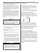

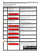
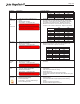
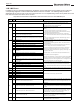
Table Of Contents
- Cover
- TABLE OF CONTENTS
- General Information
- SECTION 2 Venting and Combustion Air
- SECTION 3 Gas supply and Piping
- SECTION 4 Water Flow and Headloss Data
- SECTION 5 Boiler Piping
- SECTION 6 Condensate Drain Trap
- SECTION 7 Electrical Connections
- 7.A Installation Warnings
- 7.B Main Power Connections
- 7.C Main Power Data
- 7.D Control Panel Layout
- 7.E Field Connections
- 7.E.1 Power
- 7.E.2 Dry Contacts
- 7.E.3 Temperature Sensors
- 7.E.4 Safety Chain
- 7.E.5 Isolation Valve
- 7.E.6 Heat Demands
- 7.E.7 Analog In and Analog Out
- 7.E.8 Dry Contacts. Run & Alarm
- 7.E.9 RS 485 for Cascade (Lead Lag)
- 7.E.10 RS485 BMS
- 7.F Modbus to BACnet Memory Map (4 pages)
- 7.G WiringDiagram
- 7.H High Voltage Wiring Diagrams (5 pages)
- 7.I Ladder Diagrams (8 pages)
- SECTION 8 Control Operation
- 8.A The Home Screen
- 8.B Login to Lock / Unlock the Display Screen
- 8.C Quick Start
- 8.D Configuration
- 8.E Service Screens
- 8.E.1 Burner
- 8.E.2 Digital I/O ( Input / Output )
- 8.E.3 Analog I/O
- 8.E.4 Screen Settings Timeout
- 8.E.5 History
- 8.E.6 Restart Touchscreen & Recalibrate
- 8.E.7 Factory Reset
- 8.E.8 HMI Model OEM only
- 8.E.9 BIC Model OEM only
- 8.E.10 Both Model. OEM only.
- 8.E.11 About (the Firmware)
- 8.E.12 O2 (Trim Set Point)
- 8.E.13 LMV
- 8.F Messages and USB
- 8.G Active Demands
- SECTION 9 Parameter Tables (3 pages)
- SECTION 10 Initial startupInstructions
- SECTION 11 Maintenance
- SECTION 12 Troubleshooting
- SECTION 13 Replacement Parts
- 13.A Frame and Jacket Assembly, Part Numbers
- 13.B Control Panel Assembly, Part Numbers
- 13.C Blower and Burner Assembly,Part Numbers. ALL Sizes
- 13.D AC Distribution Box Assemblies and Part Numbers
- 13.E Burner Door Part Numbers
- 13.F Waterway Inlet Assembly, Part Numbers
- 13.G Waterway Outlet Assembly, Part Numbers
- 13.H Gas Train Part Numbers
- 13.I Exhaust Manifold Part Numbers

Page 120
LMV Error Code List
Error
Code
Diag.
Code
Meaning for the LMV3 Corrective Action
no
Comm
- No communication between the LMV3 and the AZL23
Check for a loose connection between the LMV3 and AZL23. If the
connection is good, replace the cable connecting the LMV3 to the AZL23.
If that does not fix the issue, replace the AZL23.
Any # No flame at the end of safety time (TSA)
1 No flame at the end of safety time 1 (TSA1)
2 No flame at the end of safety time 2 (TSA2)
4 No flame at the end of safety time 1 (TSA1) (software version ≤ V02.00)
Any # Extraneous light
0 Extraneous light during startup
1 Extraneous light during shutdown
2 Extraneous light during startup - prevention of startup
6 Extraneous light during startup, air pressure - start prevention
18 Extraneous light during startup, combustion pressure - start prevention
24
Extraneous light during startup, air pressure, combustion pressure - start
prevention
66 Extraneous light during startup, POC - start prevention
70 Extraneous light during startup, air pressure, POC - start prevention
82
Extraneous light during startup, combustion pressure, POC - start
prevention
86
Extraneous light during startup, air pressure, combustion pressure, POC -
start prevention
Any # Loss of flame
0 Loss of flame
3 Loss of flame (software version ≤ V02.00)
3-255 Loss of flame due to TUV test (loss of flame test)
22
OFF S
Any # Safety Loop
An enable signal was received but the LMV will not startup due to a lack
of a safety signal from the Laars Linc
50 Any # Internal error
51 Any # Internal error
55 Any # Internal error
56 Any # Internal error
57 Any # Internal error
58 Any # Internal error
Any # Internal error: No valid load controller source
No valid 4-20 mA signal is present on terminal X64. This could be done on
purpose to create a low fire hold. Otherwise, check wiring of 4-20 mA
signal and ensure 4-20 mA source is valid. See diagnostic codes for more
information.
0 Internal error: No valid load controller source Reset the fault. If the fault occurs continuously, replace the LMV3.
1 Analog output preset valid - prevention of startup
No valid 4-20 mA signal is present on terminal X64 and parameter 204 is
set to 1, causing the lockout. Re-establish a valid 4-20 mA signal and reset
the fault.
2 Analog output preset valid - default output low-fire
No fault: No valid 4-20 mA signal is present on terminal X64 and
parameter 204 is set to 0, so the LMV3 is operating at low fire. The fault
message appears to alert the user that a low fire hold is enabled. To
enable modulation, re-establish a valid 4-20 mA signal.
81 1 Interrupt limitation speed input
The LMV3 has detected an interruption on the speed input. Decrease the
electrical noise on the speed sensor wires. If the fault occurs
continuously, replace the LMV3.
Any # Error during VSD's speed standardization
An error occurred while attempting to standardize the speed of the VSD.
See diagnostic codes for more information.
Note: Diagnostic codes are additive. If a diagnostic code appears that is not on this list, it is a combination of multiple diagnostic codes.
1) Increase the setting of parameter 186:01 (fuel 0) or 187:01 (fuel 1).
This increases the FFRT. A maximum setting of 30 equals a 4 second FFRT.
2)
C
heck the flame detector signal in the presence of a known flame
source. Replace the flame detector if it does not produce the anticipated
signal.
7
4
60
If the fault occurs continuously, replace the LMV3.
2
A flame failure occurred during lightoff.
1. Check the wiring of the ignition transformer, pilot valve, and main
valve(s).
2.
C
heck manual shutoff valves for the pilot gas and main gas.
3.
C
heck the position of the air damper and close it further if necessary.
The pilot flame might be getting blown out.
4.
C
heck the flame detector signal in the presence of a known flame
source. Replace the flame detector if it does not produce the anticipated
signal.
5.
L
ow input voltage to LMV3 could cause a weak flame signal. Check
that voltage is 115-125 VAC.
An extraneous light (flame signal present when input should be de-
energized) fault occurred.
1)
En
sure that the source of light is not a flame. If it is, take corrective
action immediately.
2)
A
mbient light can cause an extraneous light fault. Ensure the flame
scanner is viewing a dark area such as the inside of a boiler.
3)
U
V scanners typically fail on (give a false flame signal). Remove UV
flame scanner and cover the bulb to ensure it is not seeing any light.
Check parameter 954 to see if the LMV3 is registering a flame signal. If it
is, replace the UV scanner.
Diagnostic code 2 - A call for heat was received, but the LMV3 will not
start up due to an extraneous light fault.
Diagnostic codes 6 and higher - A call for heat was received, but the LMV3
will not start up due to an extraneous light fault. Other inputs besides
the flame signal input are in the wrong state as well. The diagnostic code
calls out what other inputs are in the wrong state.
12.B LMV Errors.
In addition to the error messages displayed on the display unit, the LMV Status menu provides an Error Code and
corresponding Diagnostic Code associated with failures of the LMV controller. The following table provides an
abbreviated list of common LMV errors and corrective actions. For a complete listing of LMV errors please refer to the
LMV Technical Instructions which can be found at
http://www.scccombustion.com/pdf/LMV3 Technical Instructions LV3-1000 INDEXED.pdf