
Installation / Operation Instruction Manual


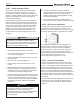

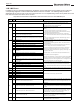
Table Of Contents
- Cover
- TABLE OF CONTENTS
- General Information
- SECTION 2 Venting and Combustion Air
- SECTION 3 Gas supply and Piping
- SECTION 4 Water Flow and Headloss Data
- SECTION 5 Boiler Piping
- SECTION 6 Condensate Drain Trap
- SECTION 7 Electrical Connections
- 7.A Installation Warnings
- 7.B Main Power Connections
- 7.C Main Power Data
- 7.D Control Panel Layout
- 7.E Field Connections
- 7.E.1 Power
- 7.E.2 Dry Contacts
- 7.E.3 Temperature Sensors
- 7.E.4 Safety Chain
- 7.E.5 Isolation Valve
- 7.E.6 Heat Demands
- 7.E.7 Analog In and Analog Out
- 7.E.8 Dry Contacts. Run & Alarm
- 7.E.9 RS 485 for Cascade (Lead Lag)
- 7.E.10 RS485 BMS
- 7.F Modbus to BACnet Memory Map (4 pages)
- 7.G WiringDiagram
- 7.H High Voltage Wiring Diagrams (5 pages)
- 7.I Ladder Diagrams (8 pages)
- SECTION 8 Control Operation
- 8.A The Home Screen
- 8.B Login to Lock / Unlock the Display Screen
- 8.C Quick Start
- 8.D Configuration
- 8.E Service Screens
- 8.E.1 Burner
- 8.E.2 Digital I/O ( Input / Output )
- 8.E.3 Analog I/O
- 8.E.4 Screen Settings Timeout
- 8.E.5 History
- 8.E.6 Restart Touchscreen & Recalibrate
- 8.E.7 Factory Reset
- 8.E.8 HMI Model OEM only
- 8.E.9 BIC Model OEM only
- 8.E.10 Both Model. OEM only.
- 8.E.11 About (the Firmware)
- 8.E.12 O2 (Trim Set Point)
- 8.E.13 LMV
- 8.F Messages and USB
- 8.G Active Demands
- SECTION 9 Parameter Tables (3 pages)
- SECTION 10 Initial startupInstructions
- SECTION 11 Maintenance
- SECTION 12 Troubleshooting
- SECTION 13 Replacement Parts
- 13.A Frame and Jacket Assembly, Part Numbers
- 13.B Control Panel Assembly, Part Numbers
- 13.C Blower and Burner Assembly,Part Numbers. ALL Sizes
- 13.D AC Distribution Box Assemblies and Part Numbers
- 13.E Burner Door Part Numbers
- 13.F Waterway Inlet Assembly, Part Numbers
- 13.G Waterway Outlet Assembly, Part Numbers
- 13.H Gas Train Part Numbers
- 13.I Exhaust Manifold Part Numbers

Page 111
Table 22. Combustion Settings.
Model Gas Type High-Fire CO
2
Low-Fire CO
2
Maximum CO (ppm)
All Models Natural 9.0% +/- 0.2%
Greater than 8.0%
& less than 9.2%
50
8. If needed, adjust the fuel pressure adjustment
screw (See Figure 51) to obtain a Hi-Fire
CO
2
measurement of 9.0% +/- 0.2%.
NOTE: Turn the adjustment screw only a
quarter turn per adjustment either up or down,
then watch the combustion analyzer for the
result.
Once the Hi-Fire CO
2
is within the range
shown above, move on to Step 9.
If the gas pressure is within range and the Hi-
Fire CO
2
will still not adjust to an acceptable
level,
then Call Factory.
9. With the High-Fire CO
2
stabilized and
acceptable at 9.0% +/- 0.2%, go to the
touchscreen display and adjust the Manual
Firing Rate to 5% for Low Fire combustion.
10. Wait until the combustion analyzer stabilizes
at the 5% rate (at least 5 minutes), to observe
the new CO
2
and CO readings. Acceptable
CO
2
at Low-Fire is ‘Greater than 8.0%
& less than 9.2%’. DO NOT ADJUST
AT LOW-FIRE.
If Low-Fire is NOT within range, then go back
to Step 5 and Repeat, adjusting only at High-
Fire.
Additionally, CO needs to be less than 50
PPM.
Check again that the incoming gas supply
pressure falls within the correct range.
See Table 23 on page 111
11. If a High-Fire CO
2
of 9.0% +/- 0.2% and at
Low Fire CO
2
of greater than 8.0% & less
than 9.2% can NOT be achieved, then call the
Manufacturer.
If these parameters have been achieved, then
12. Disable Manual Firing Rate
13. Return to the O
2
Conguration Menu and
Enable the O
2
Trim.
Table 23. Gas Pressure
Natural Gas LP (propane)
Min 4.0 IN - W.C. 8.0 IN - W.C.
Max 10.5 IN - W.C. 13.0 IN - W.C.