
Installation / Operation Instruction Manual
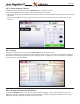
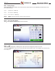
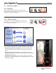
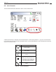
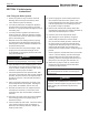
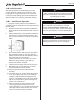
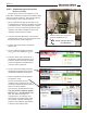
Table Of Contents
- Cover
- TABLE OF CONTENTS
- General Information
- SECTION 2 Venting and Combustion Air
- SECTION 3 Gas supply and Piping
- SECTION 4 Water Flow and Headloss Data
- SECTION 5 Boiler Piping
- SECTION 6 Condensate Drain Trap
- SECTION 7 Electrical Connections
- 7.A Installation Warnings
- 7.B Main Power Connections
- 7.C Main Power Data
- 7.D Control Panel Layout
- 7.E Field Connections
- 7.E.1 Power
- 7.E.2 Dry Contacts
- 7.E.3 Temperature Sensors
- 7.E.4 Safety Chain
- 7.E.5 Isolation Valve
- 7.E.6 Heat Demands
- 7.E.7 Analog In and Analog Out
- 7.E.8 Dry Contacts. Run & Alarm
- 7.E.9 RS 485 for Cascade (Lead Lag)
- 7.E.10 RS485 BMS
- 7.F Modbus to BACnet Memory Map (4 pages)
- 7.G WiringDiagram
- 7.H High Voltage Wiring Diagrams (5 pages)
- 7.I Ladder Diagrams (8 pages)
- SECTION 8 Control Operation
- 8.A The Home Screen
- 8.B Login to Lock / Unlock the Display Screen
- 8.C Quick Start
- 8.D Configuration
- 8.E Service Screens
- 8.E.1 Burner
- 8.E.2 Digital I/O ( Input / Output )
- 8.E.3 Analog I/O
- 8.E.4 Screen Settings Timeout
- 8.E.5 History
- 8.E.6 Restart Touchscreen & Recalibrate
- 8.E.7 Factory Reset
- 8.E.8 HMI Model OEM only
- 8.E.9 BIC Model OEM only
- 8.E.10 Both Model. OEM only.
- 8.E.11 About (the Firmware)
- 8.E.12 O2 (Trim Set Point)
- 8.E.13 LMV
- 8.F Messages and USB
- 8.G Active Demands
- SECTION 9 Parameter Tables (3 pages)
- SECTION 10 Initial startupInstructions
- SECTION 11 Maintenance
- SECTION 12 Troubleshooting
- SECTION 13 Replacement Parts
- 13.A Frame and Jacket Assembly, Part Numbers
- 13.B Control Panel Assembly, Part Numbers
- 13.C Blower and Burner Assembly,Part Numbers. ALL Sizes
- 13.D AC Distribution Box Assemblies and Part Numbers
- 13.E Burner Door Part Numbers
- 13.F Waterway Inlet Assembly, Part Numbers
- 13.G Waterway Outlet Assembly, Part Numbers
- 13.H Gas Train Part Numbers
- 13.I Exhaust Manifold Part Numbers

Page 110
Figure 43. Fuel Pressure Adjustment Screw
10.B.2 Combustion Setup Procedure
Hi-Fire, Low-Fire
The gas system must be set up properly, so the
boiler will run eciently throughout its modulation range
under the installed conditions. This setup should only
be performed by a factory trained technician.
1. Set up a gas pressure gage (monometer) on the
incoming gas line. A test plug is provided on the back
of the boiler gas line. If the gas pressure is greater
than 10.5” w.c., turn o the main gas shut-o valve
upstream of the boiler and adjust or replace fuel
regulating components as necessary.
2. Locate the pressure adjustment on the Pressure
Regulating Gas Valve by removing the brass cap at
the top front of the unit. See Figure 43
3. Install a combustion analyzer at the boiler
exhaust duct.
Remove brass cap to access fuel
pressure adjustment screw
NOTE: A quarter turn only
per adjustment.
+
-
4. On the touchscreen display navigate to
the O
2
screen and disable the O
2
Trim.
5. Provide a call for heat to terminals TT-1
and allow the system to sequence to the
Run State. Ensure that all inputs (Safety
Chain) are satised. See Digital Inputs /
Outputs in 8.E.2 on page 99
6. On the touchscreen display proceed to
the Manual Firing Rate Control Screen
and Enable the Manual Firing Control.
7. Select Firing Rate and set the Manual
Firing Rate to 100%.
Once in Run and ring at 100%,
check the CO
2
measurement on your
combustion analyzer. Be Patient! Give it
about 5 minutes to stabilize.
Also check the gas pressure at the inlet.
The gas pressure must be greater
than is 4” w. c. and less than 10.5”
w.c. See Table 23 on page 111.
If gas pressure is not sucient, shut
down system and update and/or repair
as necessary to achieve sucient gas
pressure. Once adequate gas pressure
is achieved, start again a Step 1.
100