
Installation / Operation Instruction Manual

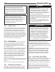


Table Of Contents
- Cover
- TABLE OF CONTENTS
- General Information
- SECTION 2 Venting and Combustion Air
- SECTION 3 Gas supply and Piping
- SECTION 4 Water Flow and Headloss Data
- SECTION 5 Boiler Piping
- SECTION 6 Condensate Drain Trap
- SECTION 7 Electrical Connections
- 7.A Installation Warnings
- 7.B Main Power Connections
- 7.C Main Power Data
- 7.D Control Panel Layout
- 7.E Field Connections
- 7.E.1 Power
- 7.E.2 Dry Contacts
- 7.E.3 Temperature Sensors
- 7.E.4 Safety Chain
- 7.E.5 Isolation Valve
- 7.E.6 Heat Demands
- 7.E.7 Analog In and Analog Out
- 7.E.8 Dry Contacts. Run & Alarm
- 7.E.9 RS 485 for Cascade (Lead Lag)
- 7.E.10 RS485 BMS
- 7.F Modbus to BACnet Memory Map (4 pages)
- 7.G WiringDiagram
- 7.H High Voltage Wiring Diagrams (5 pages)
- 7.I Ladder Diagrams (8 pages)
- SECTION 8 Control Operation
- 8.A The Home Screen
- 8.B Login to Lock / Unlock the Display Screen
- 8.C Quick Start
- 8.D Configuration
- 8.E Service Screens
- 8.E.1 Burner
- 8.E.2 Digital I/O ( Input / Output )
- 8.E.3 Analog I/O
- 8.E.4 Screen Settings Timeout
- 8.E.5 History
- 8.E.6 Restart Touchscreen & Recalibrate
- 8.E.7 Factory Reset
- 8.E.8 HMI Model OEM only
- 8.E.9 BIC Model OEM only
- 8.E.10 Both Model. OEM only.
- 8.E.11 About (the Firmware)
- 8.E.12 O2 (Trim Set Point)
- 8.E.13 LMV
- 8.F Messages and USB
- 8.G Active Demands
- SECTION 9 Parameter Tables (3 pages)
- SECTION 10 Initial startupInstructions
- SECTION 11 Maintenance
- SECTION 12 Troubleshooting
- SECTION 13 Replacement Parts
- 13.A Frame and Jacket Assembly, Part Numbers
- 13.B Control Panel Assembly, Part Numbers
- 13.C Blower and Burner Assembly,Part Numbers. ALL Sizes
- 13.D AC Distribution Box Assemblies and Part Numbers
- 13.E Burner Door Part Numbers
- 13.F Waterway Inlet Assembly, Part Numbers
- 13.G Waterway Outlet Assembly, Part Numbers
- 13.H Gas Train Part Numbers
- 13.I Exhaust Manifold Part Numbers

Page 44
0
S16
Read InletSensor AI 0 Read
°C/°F
1
S16
Read OutletSensor AI 1 Read
°C/°F
2
S16
Read FlueSensor AI 2 Read
°C/°F
3
S16
Read DHWSensor AI 3 Read
°C/°F
4
S16
Read SystemInletSensor AI 4 Read
°C/°F
5
S16
Read SystemOutletSensor AI 5 Read
°C/°F
6
S16
Read OutdoorSensor AI 6 Read
°C/°F
14
S16
Read 0‐10VDC(4‐20mA)InputforBMS AI 14 Read
mV(mA)
bit0=FlowSwitch
bit1=LWCO
bit2=MRHL
bit3=FieldInterlock
bit4=HighGasPressure
bit5=LowGasPressure
bit6=ARHL
bit7=CondensateLevel
bit0=ProofofOpen
bit1=ProofofClose
0=None
1=Anti‐ShortCycle
2=Service
3=DHW
4=Cascade
5=External
6=CH1
7=CH2
10=Anti‐Frost
11=Warmweathershutdown
bit0=Runcontact
bit1=AlarmContact
bit2=DHWPump
bit3=SystemPump
bit4=Spare
bit5=IsolationValve
bit6=AlarmBell
bit7=Boilerpump
bit8=Auxpoweredcontact
bit1=Burner1Gasvalve1
23
S16
Read 0‐10VDC(4‐20mA)OutputforPumpSpeed AI 23 Read mV(mA)
24
S16
Read 0‐10VDC(4‐20mA)OutputforFanSpeed AI 24 Read mV(mA)
28
S16
Read O2 AI 28 Read %
30
S16
Read CO2 AI 30 Read %
31
S16
Read Pressure1 AI 31 Read "W.C.
32
S16
Read Pressure2 AI 32 Read "W.C.
FLOWSWITCH=0
LOWWATERCUTOFFERROR=1
MANUALRESETHIGHLIMIT=2
PRESSURESWITCH=3
HIGHGASPRESSURESWITCH=4
LOWGASPRESSURESWITCH=5
FIELDINTERLOCK=6
SPARESAFETYCHAIN=7
OUTLETPROBELOCKOUT=8
OUTLETPROBEDRIFT=9
OUTLETPROBEHIGHLIMIT=10
FLUEPROBELOCKOUT
=11
FLUEPROBEDRIFT=13
FLUEPROBEHIGHLIMIT=14
INLETPROBELOCKOUT=15
DELTA‐T=16
GENERICLOCKOUT=17
BURNERAPSLOCKOUT=18
BURNERPARASITICFLAME=20
BURNERMAXIGNITIONATTEMPTS=22
BURNERMAXFLAMELOSS=24
NOLOCKOUT=255
24VDCERROR=30
24VACERROR=31
DHWPROBEERROR=32
SYSTEMSUPPLYPROBEERROR=33
SYSTEMRETURNPROBEERROR=34
OUTDOORPROBEERROR=35
HIGHLIMITAUTOERROR=41
36 S16 Read
35 S16 Read
20 S16 Read
ReadS1621
ReadS1622
Modbus
Address Type R/W
18 S16 Read
19 S16 Read
36 Read
Lockoutcode AI 35 Read
SafetyChainStatus
Non‐safetyChainStatus
DemandSource
GasandPilotValveStatus AI 22
AI 20
NotesMapDescriptorName
BACnet
DataType
BACnet
ObjectID R/W
Read
AI 19 Read
AI 18 Read
Read
DigitalOutputStatus AI 21 Read
ErrorCode AI
7.F Modbus to BACnet Memory Map