
Installation / Operation Instruction Manual

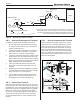


Table Of Contents
- Cover
- TABLE OF CONTENTS
- General Information
- SECTION 2 Venting and Combustion Air
- SECTION 3 Gas supply and Piping
- SECTION 4 Water Flow and Headloss Data
- SECTION 5 Boiler Piping
- SECTION 6 Condensate Drain Trap
- SECTION 7 Electrical Connections
- 7.A Installation Warnings
- 7.B Main Power Connections
- 7.C Main Power Data
- 7.D Control Panel Layout
- 7.E Field Connections
- 7.E.1 Power
- 7.E.2 Dry Contacts
- 7.E.3 Temperature Sensors
- 7.E.4 Safety Chain
- 7.E.5 Isolation Valve
- 7.E.6 Heat Demands
- 7.E.7 Analog In and Analog Out
- 7.E.8 Dry Contacts. Run & Alarm
- 7.E.9 RS 485 for Cascade (Lead Lag)
- 7.E.10 RS485 BMS
- 7.F Modbus to BACnet Memory Map (4 pages)
- 7.G WiringDiagram
- 7.H High Voltage Wiring Diagrams (5 pages)
- 7.I Ladder Diagrams (8 pages)
- SECTION 8 Control Operation
- 8.A The Home Screen
- 8.B Login to Lock / Unlock the Display Screen
- 8.C Quick Start
- 8.D Configuration
- 8.E Service Screens
- 8.E.1 Burner
- 8.E.2 Digital I/O ( Input / Output )
- 8.E.3 Analog I/O
- 8.E.4 Screen Settings Timeout
- 8.E.5 History
- 8.E.6 Restart Touchscreen & Recalibrate
- 8.E.7 Factory Reset
- 8.E.8 HMI Model OEM only
- 8.E.9 BIC Model OEM only
- 8.E.10 Both Model. OEM only.
- 8.E.11 About (the Firmware)
- 8.E.12 O2 (Trim Set Point)
- 8.E.13 LMV
- 8.F Messages and USB
- 8.G Active Demands
- SECTION 9 Parameter Tables (3 pages)
- SECTION 10 Initial startupInstructions
- SECTION 11 Maintenance
- SECTION 12 Troubleshooting
- SECTION 13 Replacement Parts
- 13.A Frame and Jacket Assembly, Part Numbers
- 13.B Control Panel Assembly, Part Numbers
- 13.C Blower and Burner Assembly,Part Numbers. ALL Sizes
- 13.D AC Distribution Box Assemblies and Part Numbers
- 13.E Burner Door Part Numbers
- 13.F Waterway Inlet Assembly, Part Numbers
- 13.G Waterway Outlet Assembly, Part Numbers
- 13.H Gas Train Part Numbers
- 13.I Exhaust Manifold Part Numbers

Page 26
SECTION 5 Boiler Piping
5.C Freeze Protection
This unit may be installed indoors or outdoors. If
installing outdoors in a location that may experience
freezing temperatures, precautions must be taken to
prevent water in the heat exchanger and condensate
inside and outside of the boiler from freezing. Damage
due to freezing water or condensate is not covered by the
warranty.
If installed indoors, and there is an event such as a
power outage, interruption of gas supply, failure of
system components, activation of safety devices, etc.,
this may prevent a boiler from ring. Any time a boiler
is subjected to freezing conditions, and the boiler
is not able to re, and/or the water is not able to
circulate, there is a risk of freezing in the boiler
or in the pipes in the system. When water freezes,
it expands. This may result in bursting of pipes, or
damage to the boiler, and this could result in leaking or
ooding conditions.
Do not use automotive antifreeze. To help prevent
freezing, the manufacturer recommends the use of
inhibited propylene glycol concentrations between
20% and 35% glycol. Typically, this concentration
will serve as burst protection for temperatures down
to approximately -5°F (-20°C). If temperatures are
expected to be lower than -5°F (-20°C), propylene
glycol concentrations up to 50% can be used. When
concentrations greater than 35% are used, water
ow rates must be increased by 15% to maintain
the desired temperature rise through the boiler.
Dierent propylene glycol products may provide
varying degrees of protection. Propylene glycol
products must be maintained properly in a heating
system, or they may become ineective. Consult the
glycol specications, or the glycol manufacturer, for
information about specic products, maintenance
of solutions, and set up according to your particular
conditions.
The following manufacturers oer propylene glycols,
inhibitors, and anti foamants that are suitable for use in
the unit. Please refer to the manufacturers instructions
for proper selection and application.
• Sentinel Performance Solutions Group
• Hercules Chemical Company
• Dow Chemical Company
5.A Boiler Water Connections
NOTE: This unit must be installed in a closed
pressure system with a minimum of 12 psi (82.7 kPa)
static pressure at the boiler.
The water piping should be supported by suitable
hangers or oor stands. Do not support the piping with
this unit. The hangers used should allow for expansion
and contraction of pipe. Rigid hangers may transmit
noise through the system resulting from the piping
sliding in the hangers. We recommend that padding be
used when rigid hangers are installed. Maintain 1” (2.5
cm) clearance to combustibles for all hot water pipes.
Suggested piping diagrams are shown in Figure 8 on
page 27 through Figure 15 on page 34 These
diagrams are meant only as guides. Components
required by local codes must be properly installed.
This unit’s eciency is higher with lower return
water temperatures. Therefore, to get the best low
return temperature with multiple boilers, pipe as shown
in Section 5.D on page 27.
Pipe the discharge of the relief valve (full size) to a drain
or in a manner to prevent injury in the event of pressure
relief. Install an air purger, air vent, expansion tank,
hydronic ow check valve in the system supply loop,
and any other devices required by local codes. The
minimum ll pressure must be 12 psig (82.7 kPa). Install
shuto valves where required by code.
5.B Cold Water Make-Up
1. Connect the cold water supply to the inlet
connection of an automatic ll valve.
2. Install a suitable back ow preventer between the
automatic ll valve and the cold water supply.
3. Install shut o valves where required.
In some installations, a hot water heating boiler is
connected to heating coils located in an air handling
unit where the coils may be exposed to refrigerated air
circulation. In these cases, the boiler piping system must
be equipped with ow control valves or other automatic
means to prevent gravity circulation of the boiler water
during the cooling cycle.
A boiler installed above radiation level, or as required by
the authority having jurisdiction, must be provided with a
low water cuto device either as a part of the boiler or at
the time of boiler installation.