
Installation / Operation Instruction Manual

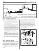


Table Of Contents
- Cover
- TABLE OF CONTENTS
- General Information
- SECTION 2 Venting and Combustion Air
- SECTION 3 Gas supply and Piping
- SECTION 4 Water Flow and Headloss Data
- SECTION 5 Boiler Piping
- SECTION 6 Condensate Drain Trap
- SECTION 7 Electrical Connections
- 7.A Installation Warnings
- 7.B Main Power Connections
- 7.C Main Power Data
- 7.D Control Panel Layout
- 7.E Field Connections
- 7.E.1 Power
- 7.E.2 Dry Contacts
- 7.E.3 Temperature Sensors
- 7.E.4 Safety Chain
- 7.E.5 Isolation Valve
- 7.E.6 Heat Demands
- 7.E.7 Analog In and Analog Out
- 7.E.8 Dry Contacts. Run & Alarm
- 7.E.9 RS 485 for Cascade (Lead Lag)
- 7.E.10 RS485 BMS
- 7.F Modbus to BACnet Memory Map (4 pages)
- 7.G WiringDiagram
- 7.H High Voltage Wiring Diagrams (5 pages)
- 7.I Ladder Diagrams (8 pages)
- SECTION 8 Control Operation
- 8.A The Home Screen
- 8.B Login to Lock / Unlock the Display Screen
- 8.C Quick Start
- 8.D Configuration
- 8.E Service Screens
- 8.E.1 Burner
- 8.E.2 Digital I/O ( Input / Output )
- 8.E.3 Analog I/O
- 8.E.4 Screen Settings Timeout
- 8.E.5 History
- 8.E.6 Restart Touchscreen & Recalibrate
- 8.E.7 Factory Reset
- 8.E.8 HMI Model OEM only
- 8.E.9 BIC Model OEM only
- 8.E.10 Both Model. OEM only.
- 8.E.11 About (the Firmware)
- 8.E.12 O2 (Trim Set Point)
- 8.E.13 LMV
- 8.F Messages and USB
- 8.G Active Demands
- SECTION 9 Parameter Tables (3 pages)
- SECTION 10 Initial startupInstructions
- SECTION 11 Maintenance
- SECTION 12 Troubleshooting
- SECTION 13 Replacement Parts
- 13.A Frame and Jacket Assembly, Part Numbers
- 13.B Control Panel Assembly, Part Numbers
- 13.C Blower and Burner Assembly,Part Numbers. ALL Sizes
- 13.D AC Distribution Box Assemblies and Part Numbers
- 13.E Burner Door Part Numbers
- 13.F Waterway Inlet Assembly, Part Numbers
- 13.G Waterway Outlet Assembly, Part Numbers
- 13.H Gas Train Part Numbers
- 13.I Exhaust Manifold Part Numbers

Page 23
2.E Outdoor Installation
This unit may be installed indoors or outdoors. If installing
outdoors in a location that may experience freezing
temperatures, precautions must be taken to prevent water
in the heat exchanger and condensate inside and outside
of the boiler from freezing. Damage due to freezing water
or condensate is not covered by the warranty.
For proper operation in outdoor installations, the
boiler must be equipped with the inlet air and exhaust
terminal kits listed in Table 11. Additional instructions are
supplied with the terminal kits.
WARNING
If installing outdoors in a location that may
experience freezing temperatures, provisions must
be made to protect the unit from freeze damage.
manufacturer does not warranty damage caused
by freezing temperatures.
2.F Installations in the Commonwealth of
Massachusetts
In Massachusetts the following items are required if the
side-wall exhaust vent termination is less than seven
(7) feet above nished grade in the area of the venting,
including but not limited to decks and porches. (From
Massachusetts Rules and regulations 248 CMR 5.08.)
1. Installation of Carbon Monoxide Detectors
At the time of installation of the side-wall vented
gas fueled unit, the installing plumber or gastter
shall observe that a hard wired carbon monoxide
detector with an alarm battery back-up is installed on
the oor level where the gas unit is to be installed.
In addition, the installing plumber or gastter shall
observe that a battery operated or hard wired carbon
monoxide detector with an alarm is installed on each
additional level of the dwelling, building or structure
served by the side-wall horizontally vented gas fueled
equipment. It shall be the responsibility of the property
owner to secure the services of qualied licensed
professionals for installation of hard wired carbon
monoxide detectors.
a. In the event that the side-wall horizontally vented
gas fueled equipment is installed in a crawl space or
an attic, the hard wired carbon monoxide with alarm
and battery back-up may be installed on the next
adjacent oor level.
(Place in section 3.1)
Model 1000 Model 1500 Model 2000 Model 3000
Screen for horizontal galvanized air pipe D2012104 D2012101 D2012101 D2012102 D2012103 D2012103
Screen for horizontal PVC air pipe CA012004 CA012001 CA012001 CA012002 CA012003 CA012003
Screen for horizontal polypropylene air pipe CA012200 CA012201 CA012201 CA012202 CA012203 CA012203
Screen for vertical galvanized air pipe D2012204 D2012201 D2012201 D2012202 D2012203 D2012203
CA012403 CA012403
CA012602
CA012603
CA012603
Table 3a - Ducted Air Accessories
Horizontal vent terminal for stainless steel D2012004 D2012001 D2012001 D2012002 D2012003 D2012003
Screen for horizontal CPVC vent CA012104 CA012101 CA012101 CA012102 CA012103 CA012103
Screen for vertical stainless steel vent CA011904 CA011901 CA011901 D2012302 D2012303 D2012303
Screen for vertical CPVC vent CA012504 CA012501 CA012501 CA012502 CA012503 CA012503
Table 3* - Vent Accessories
(Place in section 3.5)
Air intake screen for unit placed outdoors CA011904 CA011901 CA011901
Vent terminal for unit placed outdoors CA017201 CA017202 CA017202
Table 3** - Air & Vent Accessories for Units Placed Outdoors
Model 1000 Model 1500 Model 2000
D2012002
CA012102
CA011902
CA012502
Model 3000
Model 1000 Model 1500 Model 2000
CA011901
CA017203
Model 3000
Screen for vertical polypropylene air pipe CA012604 CA012601 CA012601 CA012602
Table 11. Air & Vent Accessories for units placed outdoors
b. In the event that the requirements of the subdivision
cannot be met at the time of completion of installation,
the owner shall have a period of thirty (30) days
to comply with the above requirements, provided,
however, that during said thirty (30) day period, a
battery operated carbon monoxide detector with an
alarm be installed.
2. Approved Carbon Monoxide Detectors
Each carbon monoxide detector shall comply with
NFPA 720 and be ANSI/UL 2034 listed and IAS
certied.
3. Signage
A metal or plastic identication plate shall be
permanently mounted to the exterior of the building at
a minimum height of eight (8) feet above grade directly
in line with the exhaust vent terminal for horizontally
vented gas fueled heating unit or equipment. The sign
shall read, in print no less than one-half (1/2) inch in
size: “GAS VENT DIRECTLY BELOW, KEEP CLEAR
OF ALL OBSTRUCTIONS.”
4. Inspection
The state or local gas inspector of the side-wall
horizontally vented gas fueled unit shall not approve
the installation unless, upon inspection, the inspector
observes carbon monoxide detectors and signage
installed in accordance with the provisions of 248
CMR 5.08(2)(a) 1-4.